Figure 6.12.3.1: digital outputs, Refer to paragraph 6.16.3 pid function, Brake alarm signal – GE Industrial Solutions DV-300 DC Drive Users Manual User Manual
Page 202: I2t motor overload alarm signal
GEI-100332Ga
——— FUNCTION DESCRIPTION ———
6
74
Drive Relay Output
D02
D06
27
7
COM_DO
COM_DO
25
5
D03
D07
28
8
COM_DO
COM_DO
25
5
D04
D08
29
9
COM_DO
COM_DO
25
5
R2NO
75
R2COM
76
D01
D05
26
6
COM_DO
COM_DO
25
5
R1NO
35
R1COM
36
TBO integrated (pos.” A”)
TBO card pos. B (option)
Ok relay func.
Drive healthy
Relay 2
Stop control
Digital output 1
Digital output 5
Ramp +
Curr limit state
Inversion out 2
Inversion out 6
Inversion out 3
Inversion out 7
Inversion out 4
Inversion relay 2
Inversion out 8
Inversion out 1
Inversion out 5
Digital output 2
Digital output 6
Ramp -
Overvoltage
Digital output 3
Digital output 7
Spd threshold
Undervoltage
Digital output 4
Digital output 8
Overld available
Overcurrent
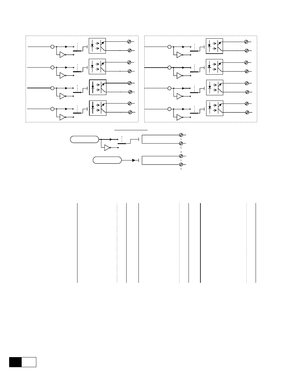
Figure 6.12.3.1: Digital outputs
Digital output XX
Selection of the parameter that is assigned to the digital output concerned. The following
assignments are possible:
OFF
Speed zero thr
Spd threshold
Set speed
Curr limit state
Drive ready
Mot ovrld avail
6)
Overload state
Ramp +
Ramp -
Speed limited
Undervoltage
Overvoltage
Heatsink
Overcurrent
Overtemp motor
External fault
Failure supply
0
1
2
3
4
5
6
7
8
9
10
11
12
13
14
15
16
17
Pad A bit
Pad B bit
Virt dig input
Torque sign
Stop control
Field loss
Speed fbk loss
Bus loss
Hw opt1 failure
Opt2 failure
Encoder 1 state
Encoder 2 state
Enable seq err
Diameter calc st
1)
Drive healthy
13)
Input 1 cp match
Diam reached
Spd match compl
18
19
20
21
23
24
25
26
28
29
30
31
35
38
42
49
58
59
Acc state
Dec state
Brake comand
2)
Brake failure
3)
Mot ovrld preal
4)
Dvr ovrld preal
5)
Dvr ovrld avail
7)
I2t mot ovrld fail
8)
I2t drv ovrld fail
9)
Mot cur threshld
10)
Overspeed
11)
Delta frequency
12)
Drv rdy to start
14)
BUS control mode
15)
60
61
62
63
65
66
67
68
69
70
71
72
76
77
1)
Refer to paragraph 6.16.3 PID function
2)
brake relay control; indicates the presence of adequate current to support the load
(Torque proving) parameter..
3)
brake alarm signal.
4)
this signal is enabled when the thermal image of the motor Motor I2t accum =
90 % and returns to 0 when Motor I2t accum = 0.
5)
this signal is enabled when the thermal image of the drive Drive I2t accum = 90
% and returns to 0 when Drive I2t accum = 0.
6)
The default condition of this signal is enabled. It is disabled when Motor I2t accum
= 100 % and is re-enabled when Motor I2t accum = 0.
7)
The default condition of this signal is enabled. It is disabled when Drive I2t accum
= 100 % and is re-enabled when Drive I2t accum = 0.
8)
I2t motor overload alarm signal.