GE Industrial Solutions DV-300 DC Drive Users Manual User Manual
Page 197
DV-300 Adjustable Speed Drives
——— FUNCTION DESCRIPTION ———
6
69
Select input XX
Selection of the parameter to be assigned its value via an analog input. The following
assignments are possible:
OFF
Jog reference
1)
Speed ref 1
1)
Speed ref 2
1)
Ramp ref 1
1)
Ramp ref 2
1)
T current ref 1
2)
T current ref 2
2)
Adap reference
1)
T current limit
2)
0
1
2
3
4
5
6
7
8
9
T current lim +
2)
T current lim -
2)
Pad 0
3)
Pad 1
3)
Pad 2
3)
Pad 3
3)
Load comp
PID offset 0
4)
PI central v3
4)
PID feed-back
4)
10
11
12
13
14
15
19
21
22
23
Flux current max
Out vlt level
Speed ratio
5)
Tension red
Tension ref
Preset 3
Brake Ref *
25
26
28
29
30
31
32
* Reference for the Torque proving parameter setting.
An in xx target
Assign the analog input xx sampling. If assigned, the sampled value is copied into the
parameter programmed on the analog input. If not assigned, the programmed parameter
takes the value preset via keypad or RS485 or BUS, before to assign an analog input.
Exception are the “PAD” parameters, where the last value on the analog input is stored
when An in XX target = not assigned is executed.
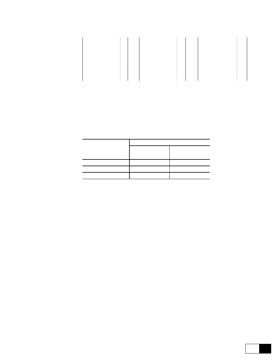
Input XX type
Selection of input type (voltage or current input)
Jumpers on the regulator card of the DV-300 should be fitted or removed according to
the input signal used. The inputs of the device are factory set for voltage signls.
Analog Input
Input Signal
-10 V ... + 10 V
0 - 10 V
0 - 20 mA
4 - 20 mA
Analog input 1
S9 = OFF
S9 = ON
Analog input 2
S10 = OFF
S10 = ON
Analog input 3
S11 = OFF
S11 = ON
GD6185g
ON
Jumper fitted
OFF
Jumper not fitted
10 V...+10 V
A voltage of max ±10 V is connected to the analog input concerned.
If the signal is used as a reference value, a polarity reversal can
be used to reverse the rotation direction of the drive (only with
6KDV3 ... Q4 converters). The 6KDV3 ... Q2 converters accept
as speed reference only positive references. Negative references
are not accepted and the drive does not start.
0-10V, 0-20mA
A voltage of max. 10 V or a current signal of 0...20 mA is
connected to the analog input concerned. The signal must be
positive. If the signal is used as a reference value for 6KDV3...
Q4 converters, the rotation direction can be reversed via the
Input XX sign + and Input XX sign - parameters.
4-20 mA
A current signal of 4...20 mA is connected to the analog input
concerned. The signal must be positive. If the signal is used as a
reference value for 6KDV3 ... Q4 converters, the drive rotation
direction can be reversed via the Input XX sign + and Input
XX sign - parameters.
Input XX sign
Selection of rotation direction when operated via the serial interface or bus for the tet-
raquadrant 6KDV3 ... Q4 converters.
Input XX sign +
Selection of “Clockwise” rotation when operated via the terminal strip for the 6KDV3...4B
converters, when the reference value is only given with one polarity.
High
Clockwise selected
Low
Clockwise not selected