Figure 4.8.2: example for relay interface – GE Industrial Solutions DV-300 DC Drive Users Manual User Manual
Page 63
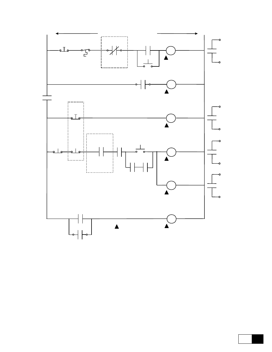
DV-300 Adjustable Speed Drives
——— WIRING PROCEDURES ———
4
19
Coil Suppressor
AC Input Contactor
K1M
ENABLE
K1MX
Drive OK
Contact closes
with power ON
FAN 560A and
above only
START
K2
FAST STOP
Drive OK
Reset
115 VAC from CPT
fed from AC incoming
START
PB
START
K2
FAN power
OK (Q1)
STOP
PB
85
86
FAST STOP
K0
Drive Healthy
picks up if OK
SNF
P.B.
latched on push, pull to reset
after the process has stopped
H
N
EXTERNAL
ESTOPS
System Not Fault
SNF
SNF
EXTERNAL
RUN
PERMISSIVES
T.D.A.D. *
- Time delay after de energization -
Set greater than the maximum
decel ramp time.
K1MX
K2
K0
SNF
19
15
19
14
19
13
19
12
+24V
+24V
+24V
+24V
EXT
FAULT
FAST
STOP
START
ENABLE
75
76
Operation set by parameter [629]
RELAY 2 and parameter [626] stop mode
K1M AUX
(MA AUX)
81
82
Blown
Fuse
560A and
above only
DV-300
Relay 2
K2
Figure 4.8.2: Example for relay interface
n
ote
!
1 - ENABLE must remained energized during a normal STOP or FAST STOP for the DV-300
to decel on a ramp.
2 - ENABLE must be de energized to power up and to reset a fault or alarm.
3 - If the external fault input, or fast stop input, is unused, the unused input must
be tied to + 24V (terminal 19).
4 - EXTERNAL FAULT input, FAST STOP input, START input and ENABLE input
need picked up during LAN operation. Opening the input will cause labeled drive
reaction.
* - T.D.A.D. = Time Delay After De energization.