GE Industrial Solutions DV-300 DC Drive Users Manual User Manual
Page 187
DV-300 Adjustable Speed Drives
——— FUNCTION DESCRIPTION ———
6
59
possible current. The converter is then disabled when stopped.
Ignore
No reaction is present. A warning message can be output via a
digital output.
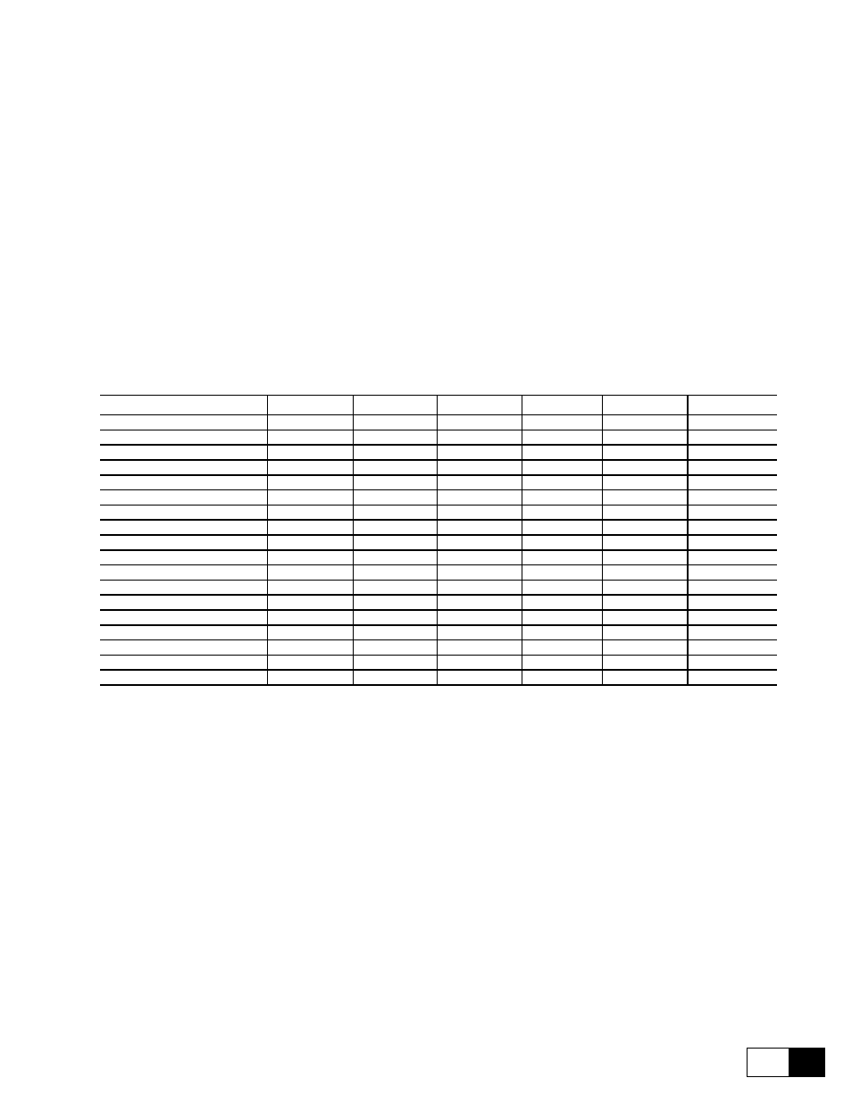
Not all alarms can initiate a controlled stop of the drive. The possibility of setting the
particular “Activity” for individual alarms is described in the table below.
Latch
ON
The alarm is stored. The programmed actions (e.g. opening
the OK relay) are enabled. This status is kept latched even if
the fault condition is restored. A Reset command is required
before a restart.
OFF
In case of alarm, the drive is disabled and the programmed
functions are enabled. The alarm is not latched. When the
failure is removed, the alarm is automatically reset and the
device tries restarting.
Ok relay open
ON
An alarm causes the opening of the potential isolated contact
between terminals 35 and 36.
OFF
The alarm does not cause the opening of the potential free
contact of the OK reay.
Alarm
Ignore
Warning
Disable drive
Quick stop
Normal stop
Curr lim stop
Failure Supply
-
-
X
-
-
-
Undervoltage
-
-
X
-
-
-
Overvoltage
X
X
X
-
-
-
Overspeed
X
X
X
X
X
X
Heatsink
-
X
X
X
X
X
Overtemp motor
X
X
X
X
X
X
External fault
-
X
X
X
X
X
Brake fault
X
X
X
X
X
X
Motor I2t ovrld
X
X
X
-
-
-
Drive I2t ovrld
-
-
X
-
-
-
Overcurrent
X
X
X
-
-
-
Field loss
X
X
X
-
-
-
Delta frequency
X
X
X
-
-
-
Speed fbk loss
-
X
X
-
-
-
Opt 2 failure
-
-
X
X
X
X
Bus loss
X
X
X
X
X
X
Hw Opt 1 failure
-
X
X
X
X
X
Enable seq err
X
-
X
-
-
-
GD6165g
Hold off time
Delay time between the alarm condition detection and the alarm activation. If an alarm
condition occurs the alarm stay OFF for the Hold off time. When this time is elapsed
and the alarm is still present, the alarm activates.
Restart time
If Latch=Off and the alarm condition persists even after the time defined via Restart
time, the alarm is stored and no restart is possible (Latch=OFF).
n
ote
!
In Terminal mode to reset the fault the terminals enable and start must be at zero voltage. The
occurrence of a failure is indicated in the display of the keypad. If “Latch”=ON is selected, a
Reset command is necessary. This can be carried out, for example, by pressing the CANCEL
key on the keypad. If a second error occurs before the first one was reset, the text “Multiple
failures” will appear in the display. In this case, a reset is only possible via Failure reset
parameter in the SPEC FUNCTIONS menu. The reset can be obtained by pressing the ENT
key with a disabled inverter.
Failure supply
Failure on the supply voltage.
It indicates a failure on the internal voltage of the regulation circuit. The message “Failure
supply” occurs if an enabled converter has no voltage on the U2 and V2 terminals. If
it is of a short duration and restored, a possible digital output prepared for the message
is set to a Low condition. A normal reset can be carried out.