12 i/o config, Figure 6.12.1: arrangement of the programmable i/o, Tbo "a” integrated – GE Industrial Solutions DV-300 DC Drive Users Manual User Manual
Page 192: Tbo "b
GEI-100332Ga
——— FUNCTION DESCRIPTION ———
6
64
The message Wrong password appears if an incorrect password is entered.
If the drive shows the message EEPROM the password is deactivated. This takes place the first time the drive
is switched on and after a possible change of the operating system.
On delivery the Service menu of the drive is protected by Password 2. No Pword 1 has been entered. The user
has free access to all parameters.
Password 2 cannot be deactivated.
n
ote
:
In case personal password has been forgotten, it is possible to deactivate it through the setting
of the universal password.
The code of this password is: 51034
The setting mode of this one remains unchanged compared to the personal password.
6.12 I/O CONFIG
ENC 1
ENC 2
3 4 5 6 7 8 9 10 11 12 13 14 15 16 17 18 19 20
1 2
23 24 25 26 27 28 29 30 31 32 33 34 37 38 39 40 41 42
21 22
Digital
input
2
Digital
input
1
Digital
input
3
Digital
input
4
Com
digital
inputs
A
Analog
output
1
Analog
output
2
Com
analog
output
1
Com
digital
outputs
A
Digital
output
1
Digital
output
2
Digital
output
3
Digital
output
4
Supply
dig
outputs
A
TBO "A” integrated
Com
analog
output
2
1 2 3 4 5 6 7 8 9 10 11 12 13 14 15
XB
1
2
19
20
TBO
Analog
output
3
Com
analog
output
3
Analog
output
4
Com
analog
output
4
Com
digital
outputs
B
Digital
output
5
Digital
output
6
Digital
output
7
Digital
output
8
Supply
dig
outputs
B
Digital
input
5
Digital
input
6
Digital
input
7
Digital
input
8
Com
digital
inputs
B
TBO "B"
Analog
input
1
Analog
input
2
Analog
input
3
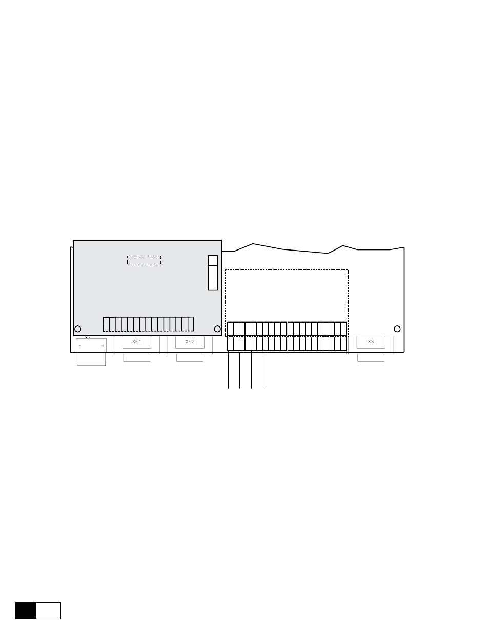
Figure 6.12.1: Arrangement of the programmable I/O
Apart from the terminals which have fixed functions (e.g. for Enables), the converters of the DV-300 series
provide the possibility of assigning freely programmable inputs/outputs to particular functions. This can either
be carried out via the keypad, the serial interface or any bus connection present.
The freely programmable inputs/outputs are factory set for assignment to the most frequently required functions.
However, these can be modified by the user accordingly to meet the requirements of the applicationn at hand.
The device inputs/outputs are subdivided as follows:
- converter with integrated TBO “A”:
3 Analog inputs (1...3), designed as differential inputs
2 Analog outputs (1 and 2) with common reference point
4 Digital outputs (1...4) with common reference point and common voltage supply
4 Digital inputs (1...4) with common reference point.