GE Industrial Solutions DV-300 DC Drive Users Manual User Manual
Page 208
GEI-100332Ga
——— FUNCTION DESCRIPTION ———
6
80
The function “Tach follower” can be used in accordance with the tabe below:
Speed fbk sel [414]
Encoder 1 as reference
Encoder 2 as reference
Encoder 1
Not available
Not available
Encoder 2
Available
Not available
Tacho
Not available
Available
Armature
Available
Available
DV0727g
n
ote
!
It is possible to set any configuration. Follow the configuration possible in the table above.
Select enc 1
These parameters define which speed reference the encoder signal will reference to.
Select enc 2
The OFF condition indicates that the encoder connector is not used as speed reference and
then it could be used as speed feedback. (CONFIGURATION/Speed fbk sel menu).
The speed reference destination choice must be done according to the speed regulator
configuration (e.g. can not use Speed ref 1 with the ramp active).
Encoder 1 type
It defines the encoder type to the XE1 connector connected.
Sinusoidal
Sinusoidal encoder
Digital
Digital encoder (DES option required)
Encoder 1 pulses
Pulse number of the encoder to the XE1 connector connected.
Encoder 2 pulses
Pulse number of the encoder to the XE2 connector connected.
Refresh enc 1
Enables the monitoring of the encoder 1 connection status, in order to detect a speed
feedback loss alarm
Refresh enc 2
Enables the monitoring of the digital encoder 2 connection status, in order to detect a
speed feedback loss alarm
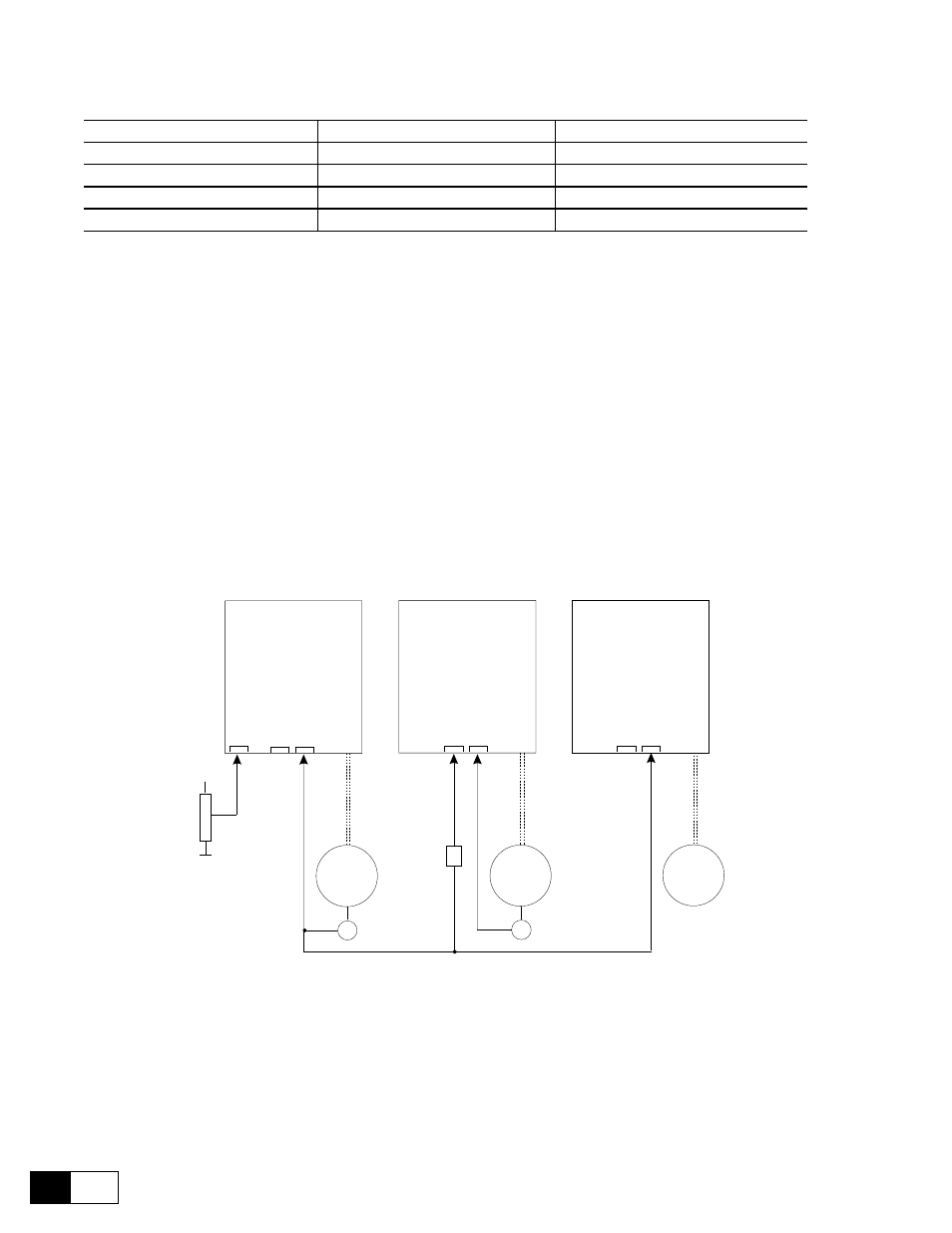
XE1
XE2
M
E
EXT REF
Drive A
(Master)
Encoder 2
XE1
XE2
M
E
Drive B
(Follower)
XE1
XE2
M
Drive C
(Follower)
Spd fbk sel
Tacho
DES
(option)
Enc 1 REF
Enc 2 REF
Enc 2
Fbk
Enc 2
Fbk
Digital encoder
Digital encoder
+
Analog
input 1
(1)
(2)
(3)
(4)
(5)
Spd fbk sel
Spd fbk sel
Encoder 2
(1) Analog inputs/ Select input 1 = Ramp ref 1
(4) Speed fbk sel = Encoder 2
(2) Speed fbk sel = Encoder 2
(5) Select enc 2 = Ramp ref 1
(3) Select enc 1 = Ramp ref 1
Figure 6.12.5.2: Example of application of the encoder reference
The Drive A speed reference is provided in this case by an external analog signal but it could be set from internal
digital sources (e.g. DGF optional card or field bus).
A configuration using the encoder signal as the line speed reference, is only possible when the speed reference
source is provided by an additional encoder, independent from the motor shaft.