GE Industrial Solutions DV-300 DC Drive Users Manual User Manual
Page 179
DV-300 Adjustable Speed Drives
——— FUNCTION DESCRIPTION ———
6
51
Enable fbk bypas
Enable of the automatic change into an armature feedback when the failure message
“Speed fbk loss” is caused by a lack of the encoder or tachometer feedback.
Enabled
Enabled automatic change
Disabled
Disabled automatic change
After an automatic change into an armature feedback, the speed regulator works with the
Speed P bypass and Speed I bypass parameters of the REG PARAMETERS/Percent
values/Speed regulator menu. The failure message “Speed fbk loss” with an enable must
be configured so that it is set as “Activity = Warning”.
Possible working only with constant field current.
Flux weak speed
Speed value as a percentage of Motor max speed, when the Voltage control phase starts.
The Flux weak speed parameter, when the speed feedback control is enabled (Enable
fbk contr = Enabled), is used to underline the fact that during the Voltage control phase
the armature voltage and the feedback signal are not proportional. If the drive works
with a constant torque on the whole regulation range (Flux reg mode = Constant Cur-
rent), it is necessary to insert the factory set 100% value.
Speed fbk error
Max. allowed error expressed as a percentage of the max. output voltage (Max out
voltage). By means of Max out Voltage, Flux weak speed and Motor nominal speed a
relation between motor speed and armature voltage is obtained. If a difference higher
than Speed fbk error occurs a Speed fbk loss failure occours.
Tacho scale
Fine scaling of the speed feedback using a tachometer analog generator (Speed fbk sel
= Tacho). It is a multiplier of the read tach voltage.
For example:
Analog tach = 60V/1000 rpm, motor top running speed 3000 rpm.
Maximum tach volts = (60V/1000 rpm*3000rpm)= 180 VDC.
- Set dip-switch S4 for 181.6V (see table 4.4.3)
- Set the tacho scale parameter = 181.6V / 180V = 1.01
- Fine adjust the value of Tacho scale if the 180 VDC tach voltage is not perfectly reached.
Speed offset
Offset scaling of the feedback circuit.
Encoder 1 pulses
Number of pulses per revolution of the sinusoidal encoder connected to the XE1 connector.
Encoder 2 pulses
Number of pulses per revolution of the digital encoder connected to the XE2 connector.
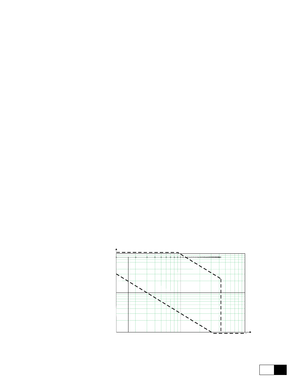
The Encoder 2 pulses and Motor max speed shall be inside the allowed area shown
in figure 6.11.4.2
100
100
200
300
400
500
600 700 800
900
1000
2000
3000
4000
200
300
400
500
600
700
800
900
1000
2000
3000
4000
5000
6000
10000
Motor max speed vs PPR
Motor
max
speed
Encoder 2 pulses
A
l l
o
w
e
d
a
r e
a
Figure 6.11.4.2: Allowed area for Encoder 2 pulses and Motor max speed
Refresh enc 1
Enable the monitoring of the encoder 1(connector XE1) connection status, in order to