Figure 4.8.3: typical connections – GE Industrial Solutions DV-300 DC Drive Users Manual User Manual
Page 64
GEI-100332Ga
——— WIRING PROCEDURES ———
4
20
+24V
V3
U3
W
V
U
M1
K1M
5
F1
1
L1
L2
L3
N
PE
*
K
2
G1
F2
C
D
0V24
1
2
3
4
6
PE
*
K1M
SMPS
A+
A-
B+
B-
*
K
0
Q1
1
3
5
2
4
6
L1
78
79
1
5
6
2
8
7
0V
24V
XE2
COMID
19
18
16
15
External
Fault
14
13
12
Faststop
Start
Enable
drive
35
(4)
36
75
76
ok
[P412]
Rela
y
2
[P629]
RS
485
7
8
9
+1
0V
-1
0V
0V
10
0V
0
Rigth
Left
R1
(2
...
5
kOhm)
2
1
3
4
5
6
Analog
input
1
Analog
input
2
-
-
+
+
Analog
input
3
-
+
W1
6KDV3...Q2
6KDV3...Q4
1
3
5
2
4
6
Q2
F12
V1
U1
D1
C1
1F1
2F2
1B1
2B2
F3
(2)
PE
PE
81
82
U2
V2
11
(1)
Keypad
(4)
Thermistor
(3)
(5)
115-230
V
A
C
230
V
A
C
FA
N
PWR
*
See
Figure
4.8.1
CNTL
PWR
Analog
outputs
1
2
21
22
23
24
Digital
outputs
1
2
3
4
25
26
27
28
29
30
Supply
Digital
inputs
35
31
32
33
34
1
2
3
4
0
V
+
2
4
V
M1-M2
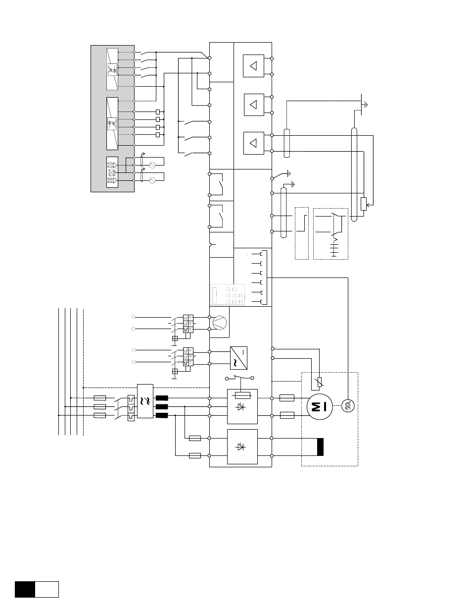
Figure 4.8.3: Typical connections
Typical wiring diagram for the standard configuration of the converter.
It is necessary to follow the instructions for mounting and wiring given in the chapters concerning engineering notes and EMC measures.
Option cards connection is not indicated here.
It is not considered the autorestart of the drive after an alarm condition.
(1) Fan with external supply only above 560/770 A included (American/European).
(2) Fuses only for 6KDV3...Q4 up to 450/650 A (American/European).
(3) 1Kohm resistor connected when the thermistor is not present.
(4) The indicated connections are relative for a digital Encoder.
(5) From 770 A (European) and 560 A (American) sizes.
Connections for sinusoidal encoder and tachogenerator are serately indicated.