Figure 6.14.6.3: example- operating point of drive – GE Industrial Solutions DV-300 DC Drive Users Manual User Manual
Page 248
GEI-100332Ga
——— FUNCTION DESCRIPTION ———
6
120
Diagram
= 0.75
for05
Base current
I
dAN
82 A
110 A
=
This means that the diagram for the converters 110 A ... 185 A with a Base current = 75
% has to be considered for the calculation.
Operating point
Basis: rated data of the converter
Overload current = 82A
. 1.8 = 147.6A
for06
= 1.34
for07
Overload current
I
(of converter)
d A N
147.6 A
110A
=
Overload factor
=
= 0.16
for08
Overload time
Pause time + Overload time
1s
5s + 1s
=
1 s
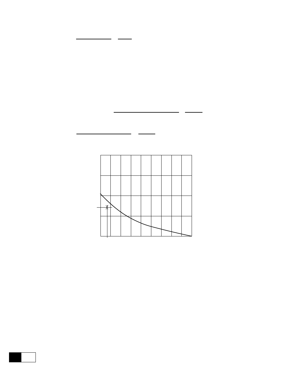
Base current = 75 % I
2,00
1,75
1,50
1,25
1,00
Overload
curren
t/
I
dAN
dAN
0,1
0,2
0,3
0,4
0,5
0,6
0,7
0,8
0,9
1,0
Overload time / (Pause time + Overload time)
Overload time
Figure 6.14.6.3: Example- Operating point of drive
The calculated operating point is below the corresponding curve for an overload time of 1 s. Therefore the con-
verter is suitable for the application. The following two settings are possible:
Full load curr
82 A
or
110 A
Enable overload
Enabled
Overload current
180 %
or
134 %
Base current
100 %
or
75 %
Overload time
1 s
Pause time
5 s
n
ote
!
The percentages for Overload current and Base current are referred to Full load curr and
not to the converter rated current!