Figure 6.7.4.2: droop function example – GE Industrial Solutions DV-300 DC Drive Users Manual User Manual
Page 165
DV-300 Adjustable Speed Drives
——— FUNCTION DESCRIPTION ———
6
37
The Droop function is used when a current balancing between two drives is required. A typical situation is when
two motors are mechanically coupled and have to run at the same speed. If, because of a different characteristic
of the two speed regulators, one of the motors is driven to run at a higher speed, it will be overloaded and the
second motor will work as a brake. The Droop function permits to avoid this bad functioning by adding a com-
ponent in the in the speed reference of the drive, which is proportional to the actual load difference of the drives.
The effect is the balancing of the two motor current.
Droop gain
Droop function gain. It is defined as a percentage of the ratio between Speed base value
ant the difference Load comp - T current ref. This means that when the difference Load
comp - T current ref is 100% and Droop gain = 100%, the speed reference correction
signal is equal to Speed base value.
Droop filter
Filter time constant
Load comp
Load compensation signal. It is typically equal to the “master” drive current, but it can
also be assigned to a programmable analog output. It is defined as a percentage of Idn.
Enable droop
Enabled
Droop function enabled.
Disabled
Droop function disabled.
Droop limit
It defines the speed reference correction range in which the droop function is active.
The value to be entered is based on the factor function.
(For more detail see Figure 6.7.1 “Speed regulator”).
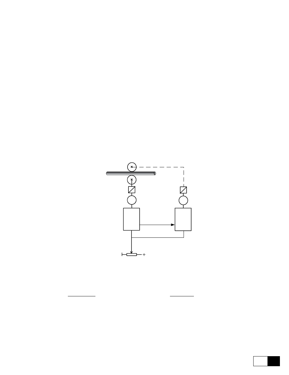
EXAMPLE (PIPE MILL)
M1
DRIVE
MASTER
LINE SPEED
M2
DRIVE
SLAVE
Analog
output
Analog
input
Figure 6.7.4.2: Droop function example
Example setting:
----> Pourpose: Torque of motor 1 has to be equal to torque of motor 2
Drive Master
Drive slave
Analog input 1= Speed ref 1
Analog input 1= Speed ref 1
Analog output 1= Tcurr ref
Analog input 2= Load comp
Enable droop= enables
Droop gain= 5%
Droop filter= 100ms
Droop limit=1000