2 terminal assignment, Table 4.7.2.3: xs1 9-pole connector – GE Industrial Solutions DV-300 DC Drive Users Manual User Manual
Page 61
DV-300 Adjustable Speed Drives
——— WIRING PROCEDURES ———
4
17
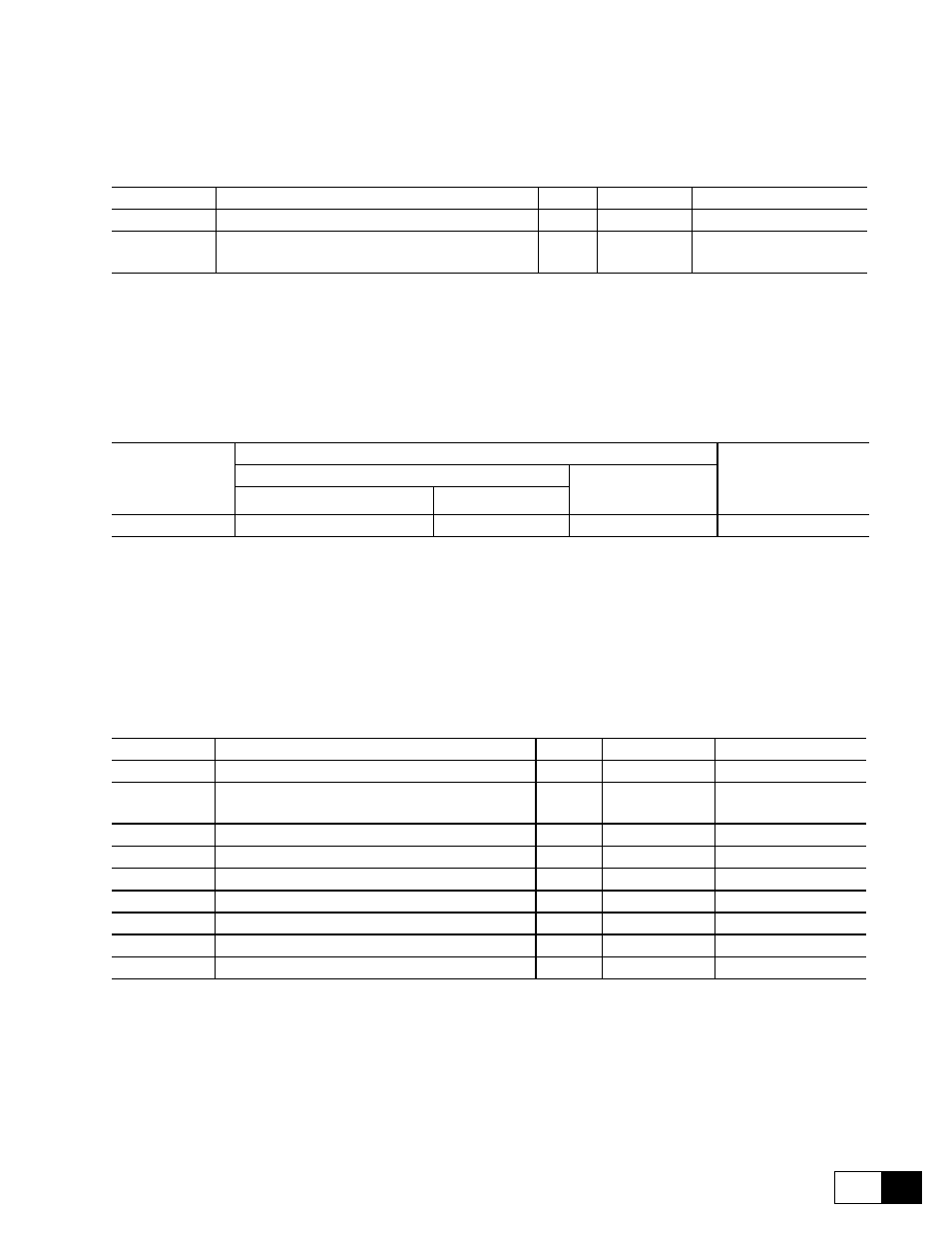
4.7.2 Terminal Assignment
Table 4.7.2.1: Terminal assignment (Terminals 0Venc and +Venc)
Designation
Function
I/O
max volt.
max curr.
0Venc
0 V supply to the encoder
I
-
-
+Venc
+15 ... 24 V supply to the encoder (S1, S2, S3 open)
+5V supply to the encoder (S1, S2, S3 closed)
I
+24V
depending on encoder data
GD0260g
I = Input O = Output
Table 4.7.2.2: Permissible cable cross section on the terminals of option card 6KDV300DES
Terminals
Max cable connection section
Tightening
torque
[Nm]
[mm
2
]
AWG
flexible
multi-core
0 Venc and +Venc
0.14 ... 1.5
0.14 ... 1.5
28 ... 14
0.5
GD0270
The use of a 3 x 0.1 x 0.02 inches (75 x 2.5 x 0.4 mm) flat screwdriver is recommended. Strip the ends of the
cables to a length of 0.26 inch (6.5 mm). Only one unprepared wire (without ferrite) should be connected to
each terminal.
Table 4.7.2.3: XS1 9-pole connector
Designation
Function
I/O
max volt.
max curr.
PIN 1
Channel B-
I
+24V
10.9mA
PIN 2
Supply voltage for the encoder (the allowed level
depends on the jumper position, see chapter 4.7.1
+24V
depending on ext. power
supply unit
PIN 3
Channel C+ (zero pulse)
I/O
+24V
10.9mA
PIN 4
Channel C- (zero pulse)
+24V
10.9mA
PIN 5
Channel A+
I/O
+24V
10.9mA
PIN 6
Channel A-
+24V
10.9mA
PIN 7
Reference point for supply voltage
I/O
-
-
PIN 8
Channel B+
+24V
10.9mA
PIN 9
not connected
I/O
-
-
GD0280g
I = Input O = Output