3 output, Output current, Armature circuit – GE Industrial Solutions DV-300 DC Drive Users Manual User Manual
Page 30: Table 2.4.3.1: output currents, Output current armature circuit
GEI-100332Ga
——— DESCRIPTION, COMPONENT IDENTIFICATION AND SPECIFICATIONS ———
2
10
2.4.3 Output
n
ote
!
It is not possible to connect an external voltage to the converter output terminals! It is not
even possible to disconnect the motor from the device output while the drive is active.
In normal cases no leveling choke is necessary. It must be taken into account, anyway, that some motor produc-
ers prescribe such a choke according to the type of the motor used. In this case it must inserted on the motor
cable.
The stated currents refer to the continuative operation with an ambient temperatrue of 104°F (40° C).
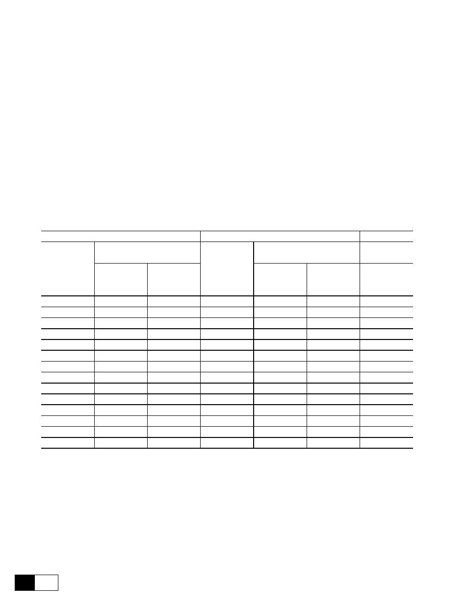
Output current
Armature circuit
Table 2.4.3.1: Output currents
American
European
Field converter
Armature current
Armature current
(Term. C1 / D1)
(Terminals C / D)
(Terminals C / D)
Continuous curr.
*Max. current
Continuous curr.
*Max. current
Continuous curr.
with Ambient
(with overload)
with Ambient
(with overload)
with Ambient
temp @ 104°F
**
temp @ 104°F
**
temp @ 104°F
6KDV3017...
17 A
34 A
6KDV3020...
20 A
40 A
10 A
6KDV3035...
35 A
70 A
6KDV3040...
40 A
80 A
10 A
6KDV3056...
56 A
112 A
6KDV3070...
70 A
140 A
10 A
6KDV3088...
88 A
172 A
6KDV3110...
110 A
220 A
14 A
6KDV3112...
112 A
224 A
6KDV3140...
140 A
280 A
14 A
6KDV3148...
148 A
296 A
6KDV3185...
185 A
370 A
14 A
6KDV3224...
224 A
448 A
6KDV3280...
280 A
560 A
20 A
6KDV3280...
280 A
560 A
6KDV3350...
350 A
700 A
20 A
6KDV3336...
336 A
672 A
6KDV3420...
420 A
840 A
20 A
6KDV3400...
400 A
800 A
6KDV3500...
500 A
1000 A
20 A
6KDV3450...
450 A
900 A
6KDV3650...
650 A
1300 A
20 A
6KDV3560...
560 A
1120 A
6KDV3770...
770 A
1540 A
25 A
6KDV3800...
800 A
1600 A
6KDV310HQ2...
1000 A
2000 A
25 A
6KDV3850...
850 A
1700A
6KDV310HQ4...
1050 A
2100 A
25 A
GD0050g
*
Current reduction for higher temperatures, see section 3.1, “Permissible ambient conditions”.
** The overload size and duration depend on the overload cycle, see section 6.14.5, “Overload control”
As for sizes above 850 / 1050 A (American / European) see Appendix A (GEI-100332C).
n
ote
!
The field motor current can sometimes be very small compared with rated field current of
the converter. In order to provide regulation during Voltage control of the motor, follow the
described instructions to change the Flux current max of the converter. In this case the Nom
field scale parameter must be set with the new rated field current value.