14 functions, 1 motorpotentiometer – GE Industrial Solutions DV-300 DC Drive Users Manual User Manual
Page 215
DV-300 Adjustable Speed Drives
——— FUNCTION DESCRIPTION ———
6
87
6.14 FuNCTIONS
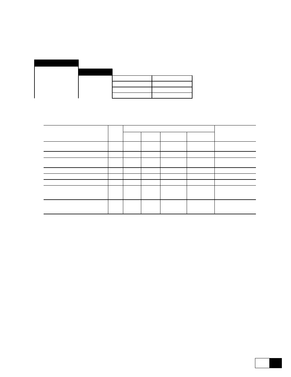
6.14.1 Motorpotentiometer
FUNCTIONS
Motor pot
[246]
Enable motor pot
[247]
Motor pot oper
[248]
Motor pot sign
[249]
Motor pot reset
The motor potentiometer function allows the speed of the drive to be adjusted by pressing a key. The speed is
then adjusted according to the defied ramp time.
Parameter description
No.
Value
Standard
Configuration
min
max
Factory
American
Factory
European
Enable motor pot
Enabled (1) / Disabled (0)
246
0
1
Disabled
Disabled
-
Motor pot oper
247
-
Motor pot sign
Positive (1) / Negative (0)
248
0
1
Positive
Positive
-
Motor pot sign +
-
**
Motor pot sign -
-
**
Motor pot reset
249
*
Motor pot up
No acceleration (0)
Acceleration (1)
396
0
1
*
Motor pot down
No deceleration (0)
Deceleration (1)
397
0
1
*
* This function can be assigned to one of the programmable digital inputs.
** This parameter can be assigned to a programmable analog output.
Enable motor pot
Enabled
The motor potentiometer function is enabled. The ramp receives
its reference value from the motor potentiometer function.
Disabled
The reference value potentiometer function is disabled.
Motor pot oper
By pressing the “+” and “-” keys of the keypad the drive can be accelerated or decelerated.
+
Accelerate
-
Decelerate
Motor pot sign
This parameter is only accessible via the keypad and via the serial interface or Bus.
When the drive is operated via the terminal strip, the parameters Motor pot sign +and
Motor pot sign - must be used. As for 6KDV3 ... Q2... converters the “Positive” func-
tion must be selected.
Positive
“Clockwise” rotation selected
Negative
“Counterclockwise” rotation selected
Motor pot sign +
Only for 6KDV3 ... Q4...! Selection of the “Clockwise” rotation direction when the
selection is carried out via the terminal strip. The Motor pot sign + parameter is linked
with the Motor pot sign - parameter via an XOR function. This means that the com-
mand (+24V) must be given only to one of the two terminals.
High
“Clockwise” rotation direction selected
Low
“Clockwise” rotation direction not selected