1 general, Fig 2.1: base diagram of a converter – GE Industrial Solutions DV-300 DC Drive Users Manual User Manual
Page 21
DV-300 Adjustable Speed Drives
——— DESCRIPTION, COMPONENT IDENTIFICATION AND SPECIFICATIONS ———
2
1
2 - desCriPTion, ComPonenT idenTifiCaTion
and sPeCifiCaTions
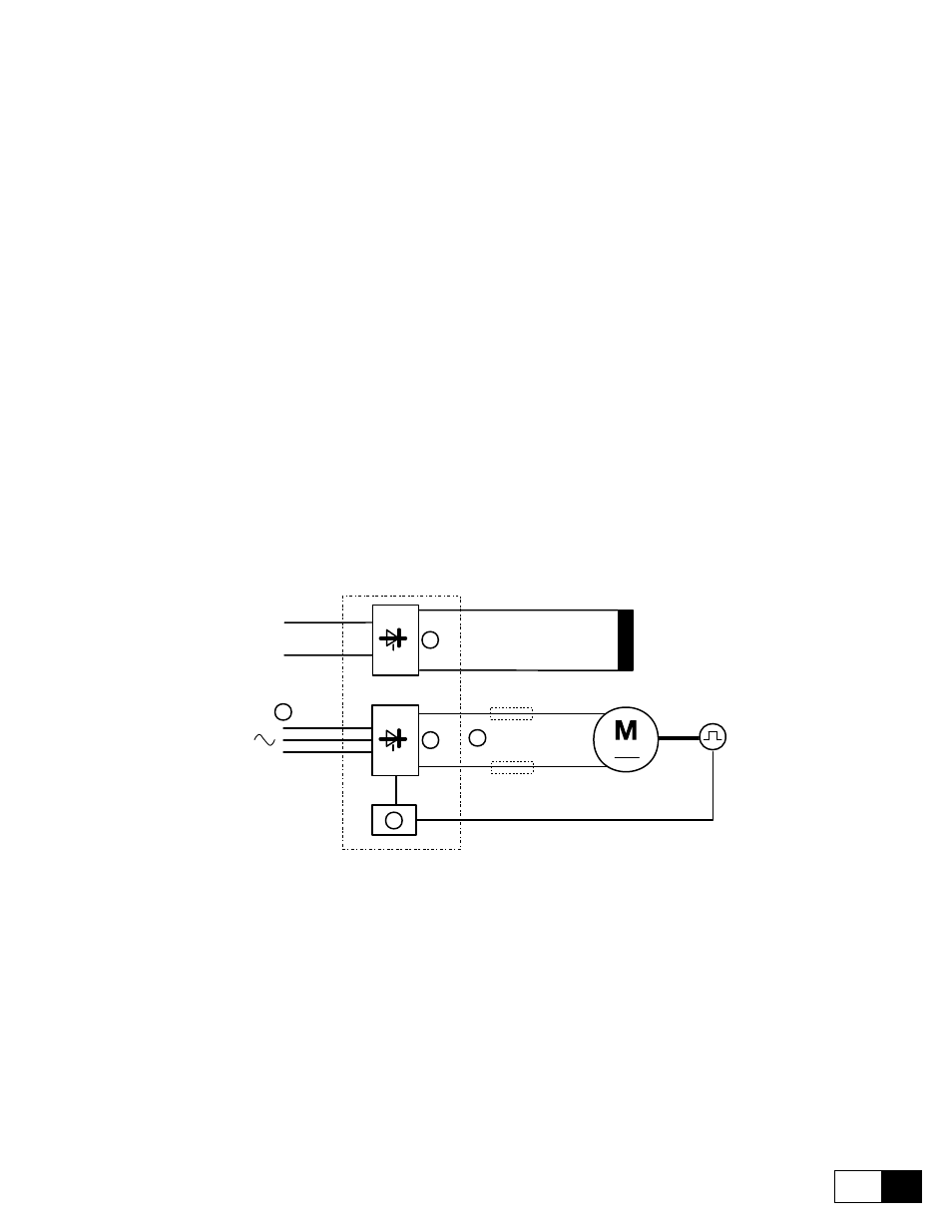
2.1 GENERAL
A converter transforms the constant voltage of an existing three-phase power supply into a direct voltage, in
order to regulate the speed and/or the torque of a direct current motor with a separate excitation.
The available DV-300 converters are of two types:
6KDV3...Q2 for a two quadrant functioning
6KDV3...Q4 for a four quadrant functioning
The default version of a converter includes the presence of a power supply circuit for the adjustable field; in this
way the motors can operate with a mixed armature or field regulation, without adding other devices.
Each type includes three series of devices, which differ the one from the other because of the max. power sup-
ply voltage:
6KDV3...Q2A...; 6KDV3...Q4E...
AC input supply voltage up to 400 V, 3Ph
6KDV3...Q2B...; 6KDV3...Q4F...
AC input supply voltage up to 500 V, 3Ph
6KDV3...Q2C...; 6KDV3...Q4G...
AC input supply voltage up to 690 V, 3Ph
1
2
3
4
5
Fig 2.1: Base diagram of a converter
AC input supply voltage:
230 V, 3Ph, 50/60 Hz
400 V, 3Ph, 50/60 Hz
460 V, 3Ph, 50/60 Hz
500 V, 3Ph, 50/60 Hz
690 V, 3Ph, 50/60 Hz
Armature converter:
Totally controlled three-phase bridge. It converts the alternating voltage
into a direct voltage. (Double bridge for 6KDV3...Q4...)
Field converter:
Semi-controlled single-phase bridge