Speed feedback setting, Dv-300 adjustable speed drives ——— block diagram, Motor – GE Industrial Solutions DV-300 DC Drive Users Manual User Manual
Page 365: Speed fbk loss armature fbk bypass
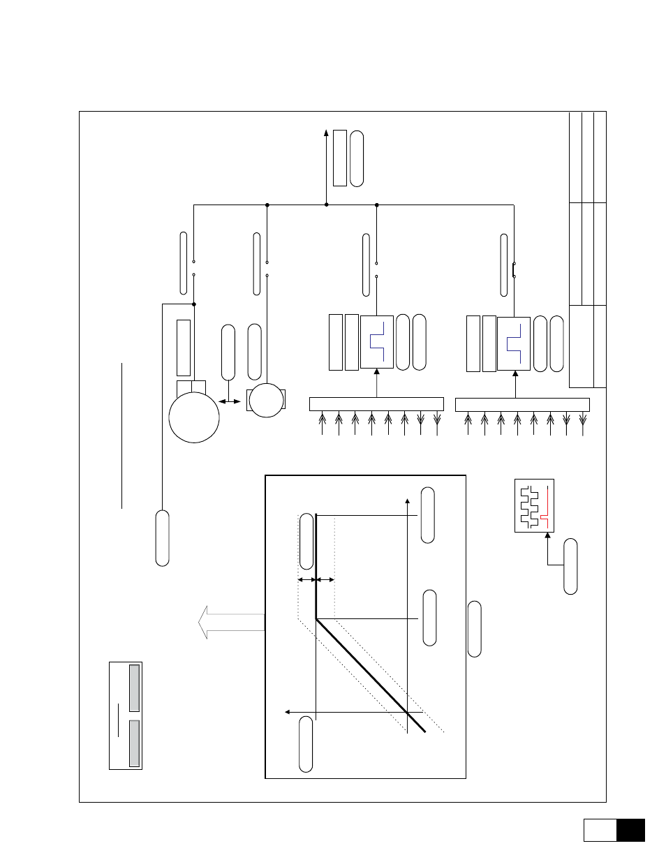
DV-300 Adjustable Speed Drives
——— BLOCK DIAGRAM ———
9
7
DV_spd_fbk.vsd
05/04/09
--
GE
User
DV
-300
DC
Digital
Drive
09.20
03/10/97
--
GE
User
File
name:
Issued
Date
---
Initials:
Revision
Date
--
Initials:
01
02
03
04
05
06
07
08
09
10
1
1
12
13
14
15
16
GE
g
Motor
s
a
nd
Industria
l
S
ystems
Salem,
V
a
.
USA
Proprietary
Information
Do
Not
Copy
PRODUCT
:
Firmware
Revision:
01
02
03
04
05
06
07
08
09
10
1
1
12
13
14
15
A
B
C
D
E
F
G
H
I
J
K
L
M
N
O
P
Q
R
S
T
U
A
B
C
D
E
F
G
H
I
J
K
L
Speed
Feedback
setting
Thi
s
is
a
verified
copy
of
controlled
documentation
printed
on
07/20/98.
The
master
is
located
on
vasald03/[vss]$/InnovCtl.
DV_Ovr_SpCur
Back
to
Overview
NA
VIGA
TION
DV_Ovw
Back
to
Overview
Speed
Index
Storing
Motor
A
H
T
acho
+
-
Speed
V
oltage
Tach generator
CEMF
Speed
fbk
loss
Armature
Fbk
Bypass
Encoder 1 Sinusoidal
6
5
1
8
4
3
A+
A-
B+
B-
C+
C-
0V
5V
XE1
connector
9
7
Encoder 1 Digital
6
5
1
8
4
3
A+
A-
B+
B-
C+
C-
0V
24
XE2
connector
2
7
Enable
ind
store
Disabled
Encoder
2
pulses
1024
R
efresh
enc
2 Disabled
Encoder
1
pulses
1024
R
efresh
enc
1 Disabled
Speed
fbk
sel
Ar
mature
Speed
fbk
sel
Encoder
1
Speed
fbk
sel
Encoder
2
Speed
fbk
sel
Tacho
En
c
1
speed
PD
output
PID
Encoder
1
state
Encode
r
2
state
Speed
offset
0
Tacho
scale
1
Actual
spd
(d)
Max.
out
voltage
500
V
Output
voltage
Enable
fbk
contr
Disabled
Flux
weak
speed
100
%
Max.
out
voltage
500
V
Motor
max
speed 2300
rpm
Speed
fbk
er
ror
22
%
Enable
fbk
bypass
Disabled
Speed Feedback setting