GE Industrial Solutions DV-300 DC Drive Users Manual User Manual
Page 55
DV-300 Adjustable Speed Drives
——— WIRING PROCEDURES ———
4
11
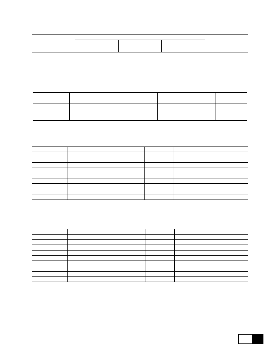
Table 4.4.7: Cable size for fans, signals, and thermistors
Terminals
Max connection cable section
Tightening torque
[Nm]
flexible [mm
2
]
multi-core [mm
2
]
AWG
1...20, +, -
0.14...1.5
0.14...1.5
26...16
0,4
GD0200g
The use of a 3 x 0.1 x 0.02 inches (75 x 2.5 x 0.4 mm) flat screwdriver is recommended. Remove 0.26 inches (6.5mm) of
the insulation at the cable ends. Only one unprepared wire (without ferrule) should be connected to each terminal.
Table 4.4.8: Terminal strip for the connection of an analog tachometer
Designation
Function
I/O
max volt.
max curr.
—
Negative tachometer input
I
—
—
+
Positive tachometer input
Clockwise rotation: positive /
counterclockwise: negative.
I
22.7 / 45.4 /
90.7 / 181.6 /
302.9 V *
8 mA
T0190g
* It depends on the section set via the Dip switch S4 (see table 4.4.3).
Table 4.4.9: Assignment of an XE1 connector for a sinusoidal encoder
Designation*
Function
I/O
max volt.
max curr.
PIN 1
Channel B-
I
1 V pp
8.3mA pp
PIN 2
Not connected
PIN 3
Channel C+ (zero pulse)
I
1 V pp
8.3mA pp
PIN 4
Channel C- (zero pulse)
I
1 V pp
8.3mA pp
PIN 5
Channel A+
I
1 V pp
8.3mA pp
PIN 6
Channel A-
I
1 V pp
8.3mA pp
PIN 7
Reference point for 5V
O
PIN 8
Channel B+
I
1 V pp
8.3mA pp
PIN 9
Supply voltage + 5V for the encoder
O
+5 V
160mA
GD0210g
*
9-pole socket connector, fitted on device. A plug connector according DIN 41 652 is required for the connection.
Table 4.4.10: Assignment of the XE2 connector for a digital encoder
Designation*
Function
I/O
max volt.
max curr.
PIN 1
Channel B-
I
30 V pp**
17mA pp
PIN 2
Supply voltage +24V for the encoder
O
24 V
200mA***
PIN 3
Channel C+ (zero pulse)
I
30 V pp**
17mA pp
PIN 4
Channel C- (zero pulse)
I
30 V pp**
17mA pp
PIN 5
Channel A+
I
30 V pp**
17mA pp
PIN 6
Channel A-
I
30 V pp**
17mA pp
PIN 7
Reference point for 24V
O
—
—
PIN 8
Channel B+
I
30 V pp**
17mA pp
PIN 9
Not connected
—
—
—
GD0220g
*
9-pole socket connector, fitted on device. A plug connector acc. DIN 41 652 is required for the connection.
** The max voltage is 30V when the S21, S22, S23 jumpers are not mounted (Encoder 15...30 V). If these jumpers are mounted
the max voltage at these Pins is 5V!
*** Total value including Terminal 19, Pin 2 of connector XE2 and the digital outputs on the option card 6KCV300TBO.