Yaskawa MEMOCON GL120 User Manual
Page 88
System Components: Functions and Specifications
4.3.2 CPU Modules: Functions and Models cont.
— 4-32 —
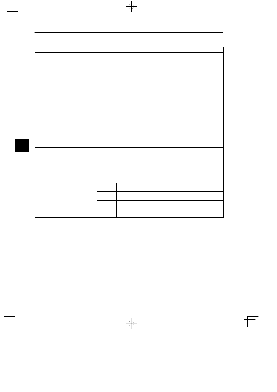
Model Name
CPU35
CPU30
CPU21
CPU20
CPU10
Maximum I/O
Points/Regis-
Digital I/O points
1,024 points max. (1 point: 1 bit) *1
4,096 points max. (1 point:
1 bit) *1
o s/ eg s
ters
I/O registers
512 registers max. (1 register: 16 bits) *2
Local I/O
1) Number of channels: 1
2) Number of Racks: 4 Racks max. including CPU Rack.
3) Number of mountable I/O Modules: 54 max.
The total number of remote I/O points and registers must meet the above
conditions *1 and *2.
Remote I/O
1) Number of channels: 2
2) Number of stations per channel: 15
3) Number of Racks per channel: 4 Racks max.
4) Number of I/O points per station:
(Digital input points ÷ 8) + (Input registers × 2) ≤ 512 bytes
(Digital output points ÷ 8) + (Output registers × 2) ≤ 512 bytes
The total number of local I/O points and registers must meet the above
conditions *1 and *2.
Maximum Capacity of Data Register
1) When the number of coils and relays is the default value, the following
condition must be met:
(Number of holding register words) + (Number of constant register words) +
(Number of link register words) ≤ 25,998
2) The maximum value of each reference can be freely set within the above limit
and the following ranges using MEMOSOFT.
Unit: word (1 word = 16 bits)
Register
Setting
Range
Setting Unit
Default
Value
Example 1
Example 2
Holding
registers
1 to
25,995
1
9,999
19,854
25,995
Constant
registers
1 to 4,096 1
4,096
4,096
1
Link
registers
1 to 4,096 1,024
2,048
2,048
0
4