Yaskawa MEMOCON GL120 User Manual
Page 218
System Components: Functions and Specifications
4.4.8 Uniwire Interface Module cont.
— 4-162 —
(3) Allocation of Register References
• Allocate registers one at a time. The maximum 17 registers can be allocated as
the total number of the input registers and the output registers.
• One input register is needed for monitoring the status of the Uniwire Interface
Module and the Uniwire System. Among the allocated input registers, the leading
register is used for monitoring the status.
Note The number of Uniwire Interface Modules that can be used depends on the num-
ber of digital references or register references that can be allocated according to
the above rules.
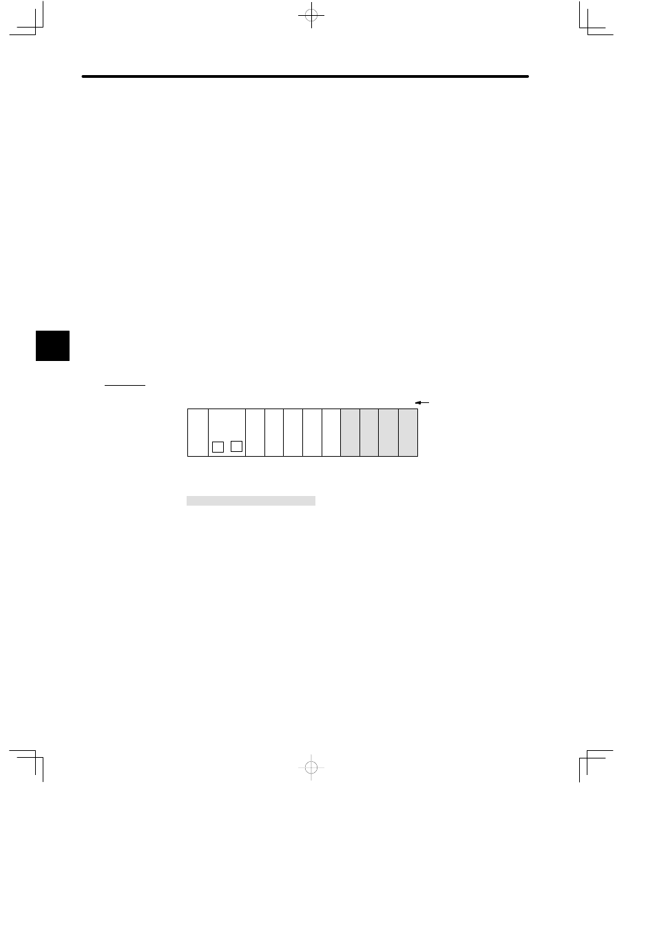
2) Installation Locations
a) A Uniwire Interface Module can be mounted to any slot of the Mounting Base of any
Rack. It will occupy one slot.
b) The following diagram shows where to mount a Uniwire Interface Module.
Example
PS05:
Power Supply Module (3 A)
CPU20:
CPU Module (16 KW)
UNI:
Uniwire Interface Module
DI:
12/24-VDC 16-point Input Module
DO:
12/24-VDC 16-point Output Module
MB12:
12-slot Mounting Base
DI
UNI
PS
05
DO
DI
M
P
MB12
Slot No.
Rack 1 (CPU Rack)
CPU20
1
2
3
4
5
6
7
8
9
10
11
12
UNI UNI
UNI
DO
Local channel
DI
Figure 4.43 Mounting Uniwire Interface Modules
4
A
EXAMPLE
"