Yaskawa MEMOCON GL120 User Manual
Page 445
!
!
6.1
Power Supply Modules
— 6-7 —
C. Input Voltage Selector Switch (AC Power Supply Modules Only)
Set the Input Voltage Selector Switch according to the range of voltage of AC power
needed supplied to the exterior power terminals (AC1, AC2), as shown in the following
diagrams.
1) When the range of voltage of AC power supply is 85 to 132 VAC:
Set the input voltage selector switch to the top as shown below.
1) PS10 selector switch
120V
2) PS05 selector switch
2) When the range of voltage of AC power supply is 170 to 264 VAC:
Set the input voltage selector switch to the bottom as shown below.
1) PS10 selector switch
2) PS05 selector switch
240V
Caution
Always make sure that there is no power being supplied to the field wiring terminals (AC1,
AC2) before you operate the input voltage selector switch.
Operating the input voltage selector switch of AC Power Supply Module while power is
being supplied to the field wiring terminals may result in damages to the AC Power Sup-
ply Module.
D. Field Wiring Terminals for AC Power Supply Modules (AC1, AC2)
Caution
Connect the correct power supply for the required ratings.
Connecting Unsuitable power supply may result in fires.
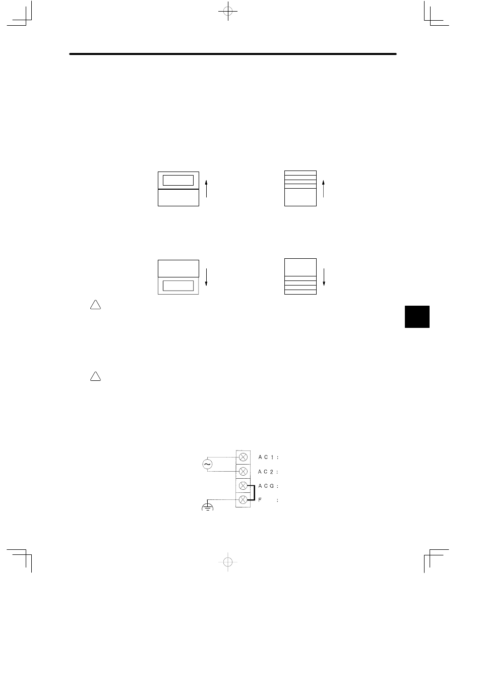
1) As shown in the following diagram, supply AC power (100 to 120 VAC or 200 to 240 VAC)
to the field wiring terminals according to the setup of the input voltage selector switch.
a) When the input voltage selector switch is set to the top
Supply AC power:
Single-phase
85 to 132 VAC
47 to 65 Hz
Filter ground terminal
Functional earth terminal
Field wiring terminal 1
Field wiring terminal 2
E
6