A.2 drilling plan – Yaskawa MEMOCON GL120 User Manual
Page 463
Appendix A Examples of Panel Layout and Hole Dimensions
— A-4 —
A.2 Drilling Plan
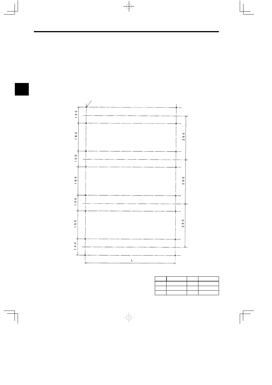
An example drilling plan for mounting four 12-slot Mounting Bases to a device mounting steel
plate is shown in the following figure. The following plan corresponds to the device layout
shown in example layout on the previous page. When the Mounting Bases are mounted to
DIN track, mount the DIN track so that the center line of the horizontal direction of the DIN
track is located in positions shown by 2-dot chain lines in the following diagram.
Center line of the horizontal direction of DIN track
Center line of the horizontal direction of DIN track
Center line of the horizontal direction of DIN track
Center line of the horizontal direction of DIN track
16-M5 Tap
(Unit: mm)
Note
Dimension L varies with the Mounting Base. The
relation between the Mounting Base and dimen-
sion L is shown at the right.
A
Base
Dimension L
MB06
MB08
280
360
Base
MB12
MB16
Dimension L
520
690
MB10
440