Yaskawa MEMOCON GL120 User Manual
Page 337
!
4.8
Other Module
— 4-281 —
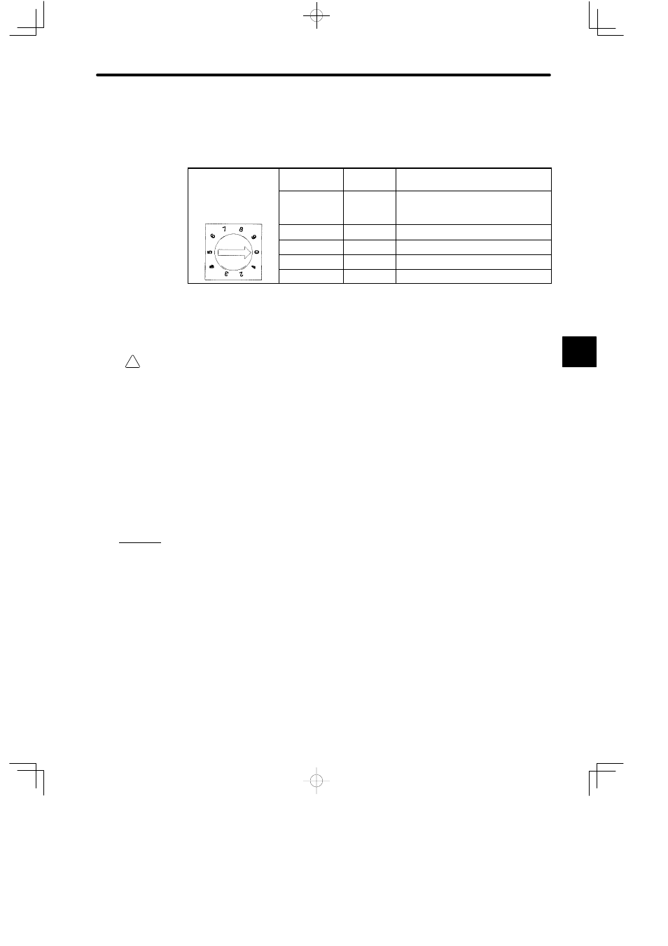
(2) The rack number is set from 1 to 4. The following table shows how to set it.
Table 4.116 Setting the Rack Number
Example
Set the rotary switch to
Rotary Switch
Setting
Rack No.
Remarks
Set the rotary switch to
0 in order to set Rack
No. 1.
0
1
Always set the Rack to which the CPU
Module and Remote I/O Receiver
Modules are mounted to Rack No.1.
1
2
2
3
3
4
4 to 9
:
Do not use.
(3) The setting of the rack number setting switch is effective (read) when the power is
turned ON to the Power Supply Module of the Rack to which the Expander Mod-
ule is mounted.
Caution
Always set the rack number using the following rules.
If you set the rack number without following these rules, the PLC System will not operate
correctly, i.e., the CPU Module may stop, and communications errors, I/O process errors,
and other error may occur.
• Set the rack number to from 1 to 4.
• The Rack on which the CPU Module and Remote I/O Receiver Modules are mounted must
always be set to rack number 1 by setting the rotary switch to 0.
• Do not use the same rack number more than once at the same station.
e) A rack number setting example is shown in the following figure.
4
A
EXAMPLE
"