Yaskawa MEMOCON GL120 User Manual
Page 151
Ver.
B01
4.3 CPU Modules
— 4-95 —
3) Pins are effective at the following times:
a) Pins 1 to 4: Whenever the pin is turned ON.
b) Pins 5 and 6: When AC power is turned ON to the Power Supply Module on the CPU
Rack.
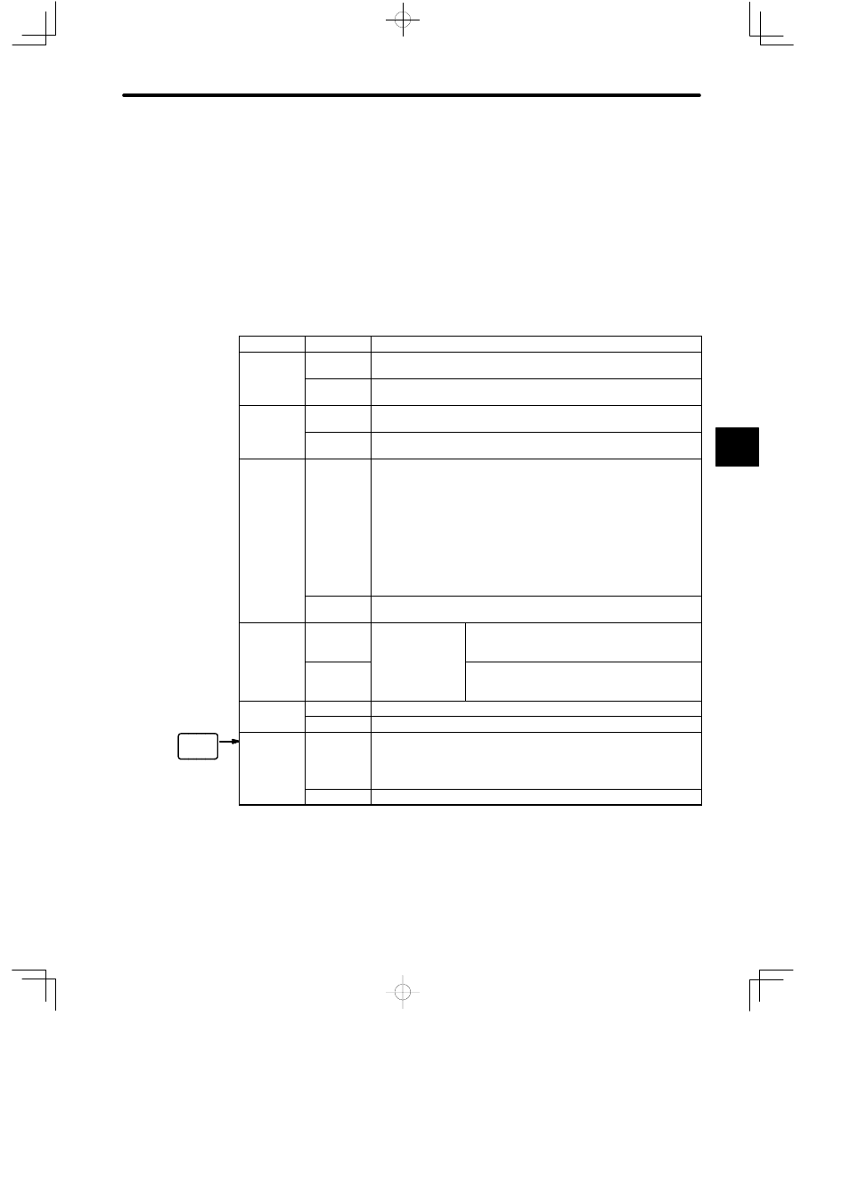
4) Each pin’s function is shown in the following table. Refer to the following pages for details.
Table 4.36 Function of DIP Switch Pins
Pin No.
Setting
Function
1
ON
Sets the communications mode and parameters of MEMOBUS port 1
to the defaults.
OFF
Sets the communications mode and parameters of MEMOBUS port 1
to the user settings.
2
ON
Sets the communications mode and parameters of MEMOBUS port 2
to the defaults.
OFF
Sets the communications mode and parameters of MEMOBUS port 2
to the user settings.
3
ON
1) Sets MEMOBUS port 2 as a master port.
2) Master communications will be enabled and slave
communications will be disabled when the CPU10 Module is in
RUN mode. Turn ON this pin to use the COMM instructions for
MEMOBUS port 2.
3) Master communications will be disabled and slave
communications will be enabled when the CPU10 Module is in
STOP mode.
OFF
Sets MEMOBUS port 2 as a slave port. Master communications will
be disabled.
4
ON
Effective when pin
3 is ON.
Sets the communications mode to Transparent
Mode when using MEMOBUS port 2 as a
master port.
OFF
Sets the communications mode to MEMOBUS
Mode when using MEMOBUS port 2 as a
master port.
5
ON
Sets the start mode of CPU10 Module to automatic RUN operation.
OFF
Sets the start mode of CPU10 Module to normal operation.
6
ON
1) Sets the CPU10 Module to ROM operation. (Ver. B01 onwards)
2) The CPU10 Module will start in STOP mode if the program data
and other data is not stored in ROM. (Ver. B01 onwards)
OFF
Sets the CPU10 Module to RAM operation. (Ver. B01 onwards)
4