Yaskawa MEMOCON GL120 User Manual
Page 350
System Components: Functions and Specifications
4.8.2 Battery Module cont.
— 4-294 —
Note
(1) Be very careful not to damage the board when pulling out the front panel.
(2) Do not apply unnecessary force to the case.
(4) Remove the connector at the end of the battery’s lead from the connector at the
board side, and remove the battery from the battery holder.
(5) Put the replacement battery in the battery holder, and connect the connector at
the end of the battery’s lead to the connector (i.e., to the connector pins) at the
board side.
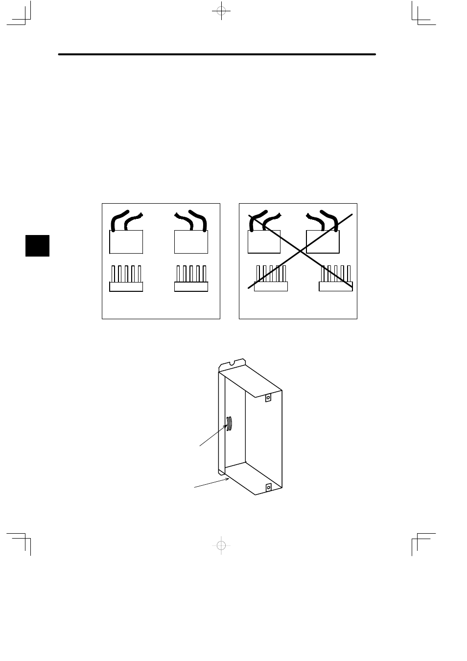
The orientation of the connector makes no differences as long as the battery con-
nector is lined up with the connector at the board side. Failure to line up these
connectors may result in malfunction.
5
1
5
1
5
1
5
1
5
1
5
1
5
1
5
1
The connector can be in any orientation as
long as the battery connector is lined up with
the connector at the board side properly.
Malfunction may result if the battery
connector is not lined up with the con-
nector at the board side properly.
(6) Attach the front panel by pressing the board into the case so that the board fits into
the board support at the back of the case.
Board support
Case
4