Yaskawa MEMOCON GL120 User Manual
Page 443

6.1
Power Supply Modules
— 6-5 —
6.1.3 Functions and Specifications of Power Supply Modules
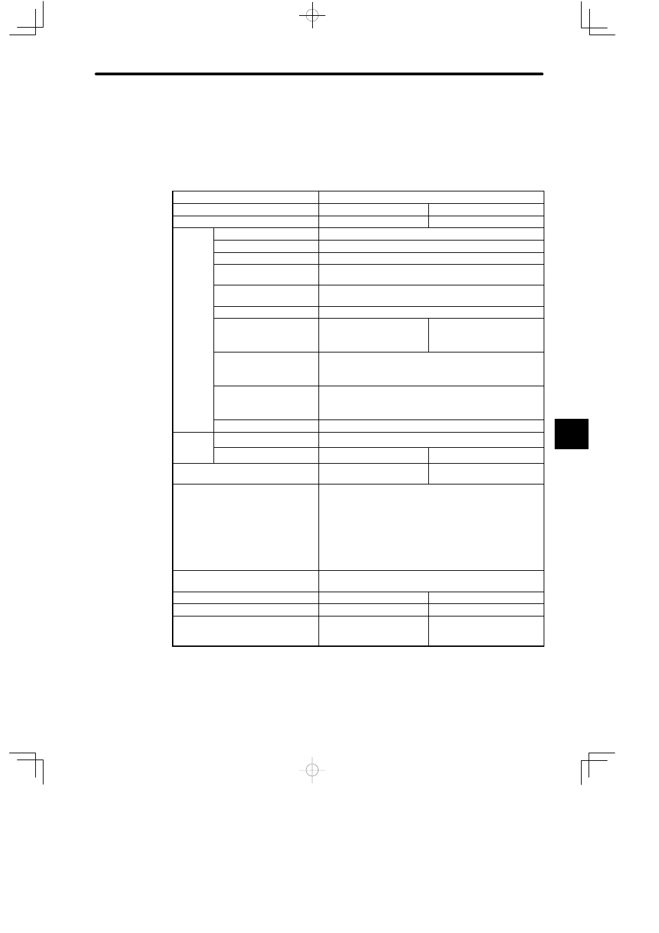
Low Voltage Directives PS05 and PS10 specifications are shown in the following table.
Table 6.2 Specifications of PS05 and PS10
Item
Specifications
Model Name
PS05
PS10
Model No.
JRMSP-120CPS11109
JRMSP-120CPS11309
Input
Rated Voltage
100 to 120 VAC or 200 to 240 VAC (Selectable)
p
Permissible Voltage Range 85 to 132 VAC or 170 to 264 VAC
Rated Frequency
50/60 Hz
Permissible Frequency
Range
47 to 63 Hz
Permissible Momentary
Power Interruption Time
Less than one cycle. Momentary power interruption intervals
must be 1 s.
Wave Distortion Factor
10% or less
Power Consumption
1) At 100 VAC: 60 VA max.
2) At 200 VAC: 75 VA max.
1) At 100 VAC: 100 VA max.
2) At 200 VAC: 120 VA max.
Current Leakage
1) At 132 VAC: 1.4 mA max.
2) At 264 VAC: 2.8 mA max.
Inrush Current
1) At 132 VAC, cold start: 25 A max.
2) At 264 VAC, cold start: 50 A max.
No. of Phases
Single-phase
Output
Charac-
Rated Voltage
5.1 VDC
Charac-
teristics
Rated Current
3.0 A
7.0 A
Fuse
Standard fusing glass tube
fuse (250 VAC, 2.0 A)
Standard fusing glass tube
fuse (250 VAC, 3.15 A)
Field Wiring Terminals
1) Equipped with three types of terminals, field wiring
terminals (AC1, AC2), filter ground terminal (ACG), and
functional earth terminal (FE).
2) M4 Phillips screws are used for the terminals.
3) Use wire size 1.5 mm
2
(AWG16) to 2.5 mm
2
(AWG13) to
connect to the terminals.
Hot Swapping
(Removal/Insertion Under Power)
Not permitted.
Maximum Heating Value
10 W
20 W
Approximate Mass
350 g
600 g
External Dimensions
Width:
40.3 mm
Height:
130 mm
Depth:
103.9 mm
Width:
81 mm
Height:
130 mm
Depth:
103.9 mm
6
