Yaskawa MEMOCON GL120 User Manual
Page 196
System Components: Functions and Specifications
4.4.6 MEMOBUS Modules (RS-422) cont.
— 4-140 —
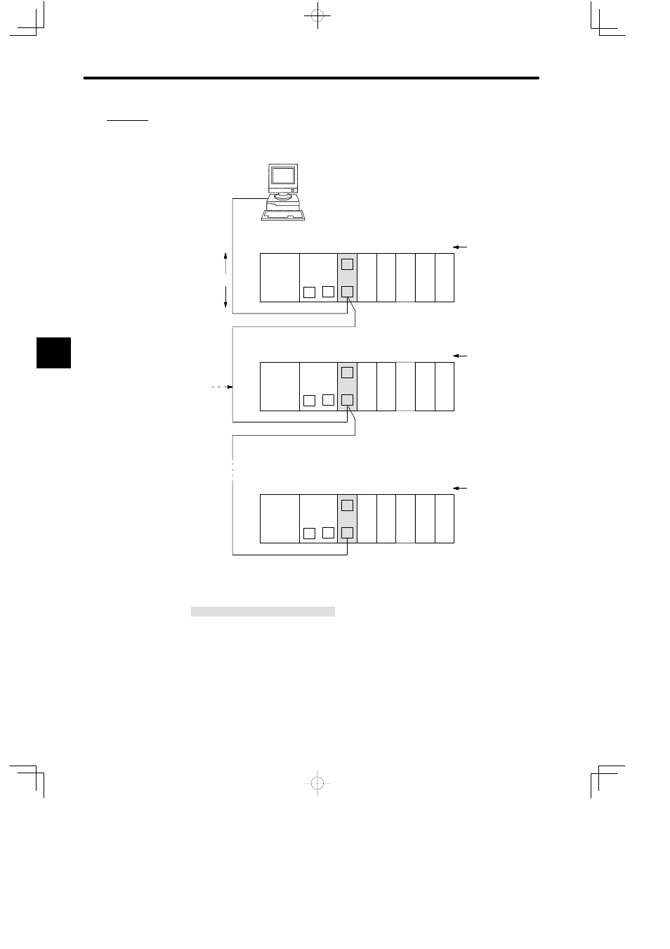
Example 2
Connecting ACGC4250 FA Monitor (1:31 Communications)
PS10:
Power Supply Module (7A)
CPU20:
CPU Module (16 KW)
CPU30:
CPU Module (32 KW)
MEM422: MEMOBUS Module (RS-422)
DI:
12/24-VDC 16-point Input Module
DO:
12/24-VDC 16-point Output Module
MB10:
10-slot Mounting Base
Shielded twisted
pair cable
*500 m max.
DI
Monitor
information
Setting
information
ACGC4250 FA Monitor
(RS-422 interface used)
M
PS10
DI
MEM
422
M
M
P
MB10
Slot No.
Local channel
Rack 1 (CPU Rack)
CPU20
1
2
3
4
5
6
7
8
9
10
DI
DO DO
M
* MEMOBUS ports of MEMOBUS Module
are set on slave ports (address 1).
Master
Communications
by MEMOBUS
protocol
*Slaves (31 max.)
DI
M
PS10
DI
MEM
422
M
M
P
MB10
Slot No.
Local channel
Rack 1 (CPU Rack)
CPU30
1
2
3
4
5
6
7
8
9
10
DI
DO DO
M
* MEMOBUS ports of MEMOBUS Module
are set on slave ports (address 2).
DI
M
PS10
DI
MEM
422
M
M
P
MB10
Slot No.
Local channel
Rack 1 (CPU Rack)
CPU20
1
2
3
4
5
6
7
8
9
10
DI
DO DO
M
* MEMOBUS ports of MEMOBUS Module
are set on slave ports (address 31).
Figure 4.34 Connecting ACGC4250 FA Monitor (1: 31 communications)
4
A
EXAMPLE
"