Yaskawa MEMOCON GL120 User Manual
Page 355

4.9
Mounting Base
— 4-299 —
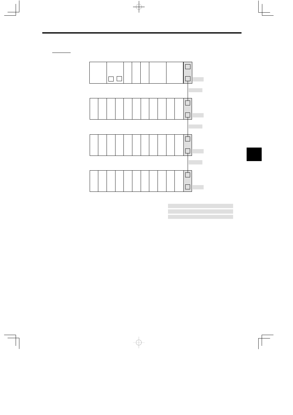
(1) An example of connecting Mounting Bases is shown in the following diagram:
MB12
DI
EXP
DI
PS
05
EXP
PS10
DO
DI
M
P
W0100-02
MC20
MC20
Rack 2
Rack 1 (CPU Rack)
DI
DI
DI
DI
DI
DI
DI
DI
DI
MB12
CPU30
EXP
DI
PS
05
W0100-02
Rack 3
DI
DI
DI
DI
DI
DI
DI
DI
DI
MB12
EXP
DO
PS
05
W0100-02
Rack 4
DO DO DO DO DO DO DO DO DO
MB12
PS10:
Power Supply Module (7 A)
PS05:
Power Supply Module (3 A)
CPU30: CPU Module (32 KW)
DI:
12/24-VDC 16-point Input Module
DO:
12/24-VDC 16-point Output Module
MC20:
4-axis Motion Module
EXP:
Expander Module
MB12:
12-slot Mounting Base
W0100-02: Rack-to-rack I/O Cable (0.2m)
Local channel
Figure 4.93 Connecting Mounting Bases
b) Mounting Position
Mounting Bases can be mounted on either one of the followings: For further details,
refer to 5.2.1 Installing Mounting Bases.
(1) On the surface of a control panel or operation panel (metal sheet)
(2) To DIN track
4
A
EXAMPLE
"
