Cpu module installation location – Yaskawa MEMOCON GL120 User Manual
Page 121
4.3 CPU Modules
— 4-65 —
4.3.4 Using CPU Modules 1 (For CPU20, CPU30, and CPU35)
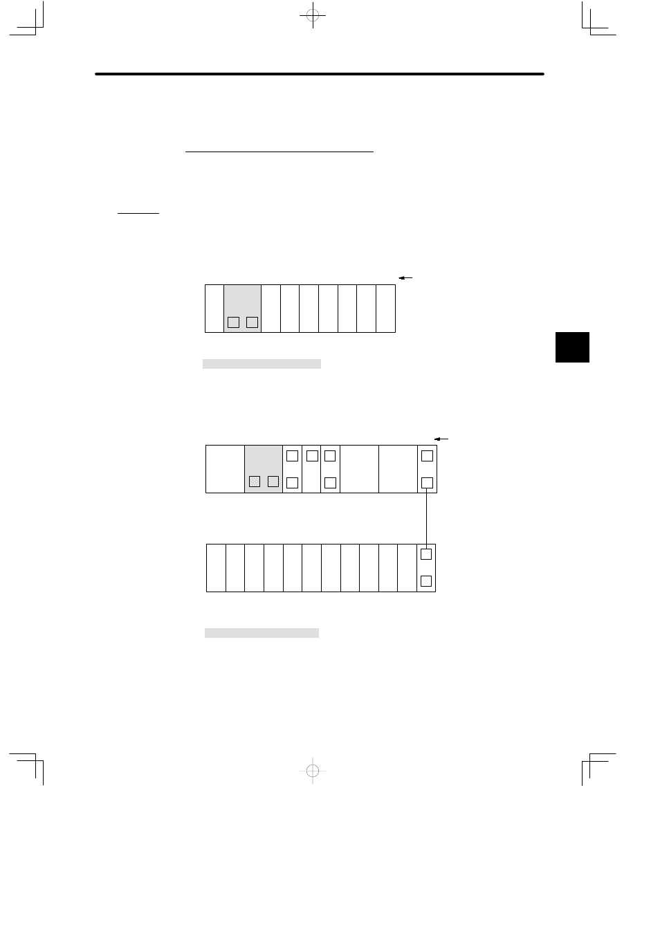
1. CPU Module Installation Location
1) The CPU Module can be mounted to any slot on the Mounting Base of Rack 1. It will
occupy 2 slots of the Rack.
2) As shown in Example 1 and Example 2 below, the CPU Module is normally mounted to
the slots on the left next to the Power Supply Module on Rack 1.
Example 1
PS05:
Power Supply Module (3 A)
CPU20:
CPU Module (16 KW)
MB10:
10-slot Mounting Base
DI:
12/24 VDC 16-point Input Module
DO:
12/24 VDC 16-point Output Module
M
P
DI
PS
05
Slot No.
Rack 1 (CPU Rack)
DI
DI
DI
DO DO DO
MB10
CPU20
1
2
3
6
7
8
9
10
4
5
Example 2
M
EXP
DI
PS
05
EXP
PS10
C
LNC
M
MEM
232
M
M
P
MB12
Slot No.
W0100-02
MC20
MC20
Rack 2
Rack 1 (CPU Rack)
DI
DI
DI
DI
DI
DO DO DO DO
MB12
CPU30
1
2
3
4
5
6
7
8
9
10
11
12
C
RDC
1
2
3
4
5
6
7
8
9
10
11
12
PS10:
Power Supply Module (7 A)
PS05:
Power Supply Module (3 A)
CPU30:
CPU Module (32 KW)
MEM232: MEMOBUS Module (RS-232)
RDC:
Remote I/O Driver Module
LNC:
PC Link Module
DI:
12/24-VDC 16-point Input Module
DO:
12/24-VDC 16-point Output Module
MC20:
4-axis Motion Module
EXP:
Expander Module
MB12:
12-slot Mounting Base
W0100-02:Rack-to-rack I/O Cable (0.2 m)
M
P
Figure 4.13 Example of Mounting CPU Modules
4
A
EXAMPLE
"