Yaskawa MEMOCON GL120 User Manual
Page 320

System Components: Functions and Specifications
4.7.3 One-axis Motion Module cont.
— 4-264 —
Table 4.109 Applicable Yaskawa Servo Amplifiers
AC Servo Series
Model Number
Σ Series
SGDj-jjj
Σ Series
DRj-jjjj
Σ-II Series
SGDM-jjj
Σ-II Series
SGDH-jjj
M, F, G, D, S, R ,P Series
CACR-SRjjjj
VS-866
CIMR-SVJ-jAj
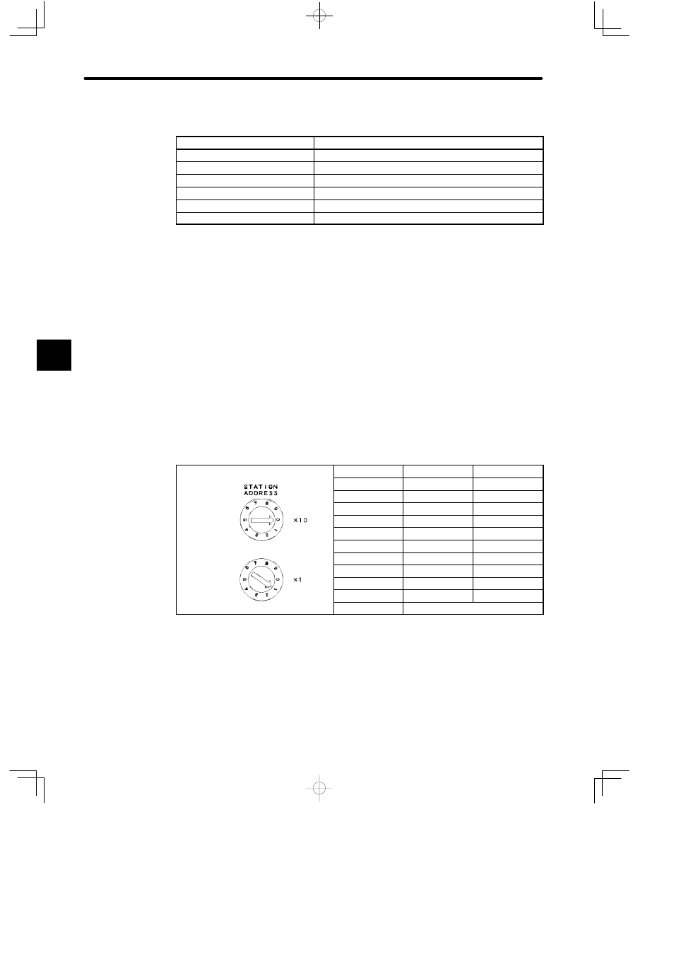
5) Rotary Switches
a) The rotary switches are used to set the Module number of the One-axis Motion Mod-
ule.
b) There are two rotary switches. The top switch is rotary switch 1 and the bottom switch
is rotary switch 2. Each switch has positions numbered from 0 to 9.
c) The setting of the rotary switches is effective (read) when the current is turned ON to
the Power Supply Module of the Rack on which the One-axis Motion Module is
mounted.
d) The Module number may be set from 1 to 99. The following table shows how to set it:
Table 4.110 Setting the Module Number
Example: Settings of Module No. 1
Module No.
Rotary switch 1 Rotary switch 2
Example: Settings of Module No. 1
1 to 9
0
1 to 9
10 to 19
1
0 to 9
20 to 29
2
0 to 9
Rotary switch 1
30 to 39
3
0 to 9
y
40 to 49
4
0 to 9
50 to 59
5
0 to 9
60 to 69
6
0 to 9
R t
it h 2
70 to 79
7
0 to 9
Rotary switch 2
80 to 89
8
0 to 9
90 to 99
9
0 to 9
0
Do not use.
Note
The same Module number must not be used more than once. If the same Module number is
used more than once, programming devices cannot set parameters and therefore cannot
monitor the parameters of the Modules whose numbers are the same.
4
