Yaskawa MEMOCON GL120 User Manual
Page 152
System Components: Functions and Specifications
4.3.6 Using CPU Modules 3 (For CPU10) cont.
— 4-96 —
5) Setting Pin 1
a) Pin 1 is used to set communications parameters for MEMOBUS port 2. Set it to meet
the requirements of your system.
Table 4.37 Setting Communications Parameters for MEMOBUS Port 1
Pin 1
Function
ON
Sets communications mode of MEMOBUS port 1 to RTU and sets the
communications parameters for the MEMOBUS port 1 to the RTU mode defaults
shown below:
1) Slave address: 1
2) Baud rate:
9,600 bps
3) Parity check:
Yes
4) Parity:
Even
5) Stop bits:
1
6) Data bit length:
8
7) Delay time:
0 ms
OFF
Enables the user to define and set the communications mode and
communications parameters for the MEMOBUS port 1 through a programming
device (Programming Panel, personal computer, etc.).
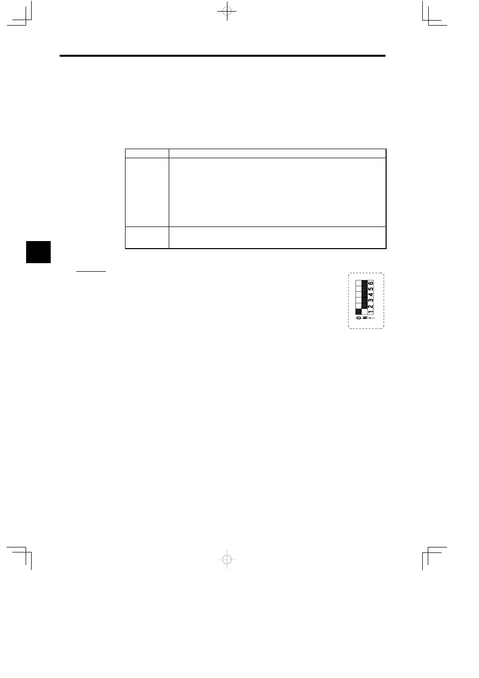
b) A setting example of pin 1 is shown below.
(1) When the DIP switch pin 1 is set as shown in the diagram on
the right, the communications parameters of MEMOBUS
port 1 are set to the RTU mode defaults shown below:
Communications Mode: RTU
Communications Parameters
Slave address: 1
Baud rate:
9,600 bps
Parity check:
Yes
Parity:
Even
Stop bits:
1
Data bit length: 8
Delay time:
0 ms
(2) When connecting a Programming Panel to the CPU10 Module, the communica-
tions parameters must match the above values (except the delay time).
4
A
EXAMPLE
"