Yaskawa MEMOCON GL120 User Manual
Page 329
4.7 Motion Modules
— 4-273 —
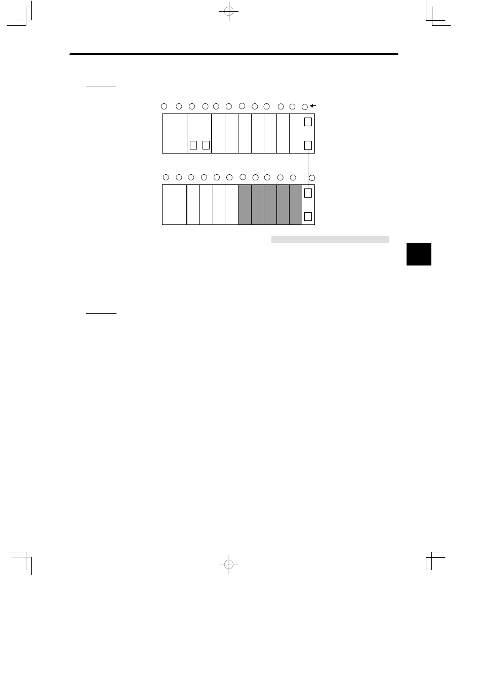
b) The following diagram shows an example of mounting Two-axis Motion Modules.
PS10
CPU30
M
P
DI
DI
DI
DI
DI
DI
DI
EXP
MB12
W0100−02
PS10
DO
DO
EXP
MB12
DO
DO
MC
15
MC
15
MC
15
MC
15
MC
15
Slot No.
Rack 2
Local channel
PS10:
Power Supply Module (7 A)
CPU30:
CPU Module (32 KW)
DI:
12/24 VDC 16-point Input Module
DO:
12/24 VDC 16-point Output Module
MC15:
2-axis Motion Module
EXP:
Expander Module
MB12:
12-slot Mounting Base
W0100-02:Rack-to-rack I/O Cable (0.2m)
Rack 1 (CPU Rack)
1
2
3
4
5
6
7
8
9
1
1
0
1 12
1
2
3
4
5
6
7
8
9
10 11
12
3) Example System Configuration
a) The following page illustrates an example of a system configuration with a Two-axis
Motion Module applied for controlling a servomotor with an absolute encoder.
b) When a Two-axis Motion Module is used to control a servomotor with an incremental
encoder, the Battery Module (Model JRMSP-120XCP96000) is not required.
4
A
EXAMPLE
"
A
EXAMPLE
"