6 mounting base layout – Yaskawa MEMOCON GL120 User Manual
Page 365

Installation and Wiring
5.1.6 Mounting Base Layout
— 5-8 —
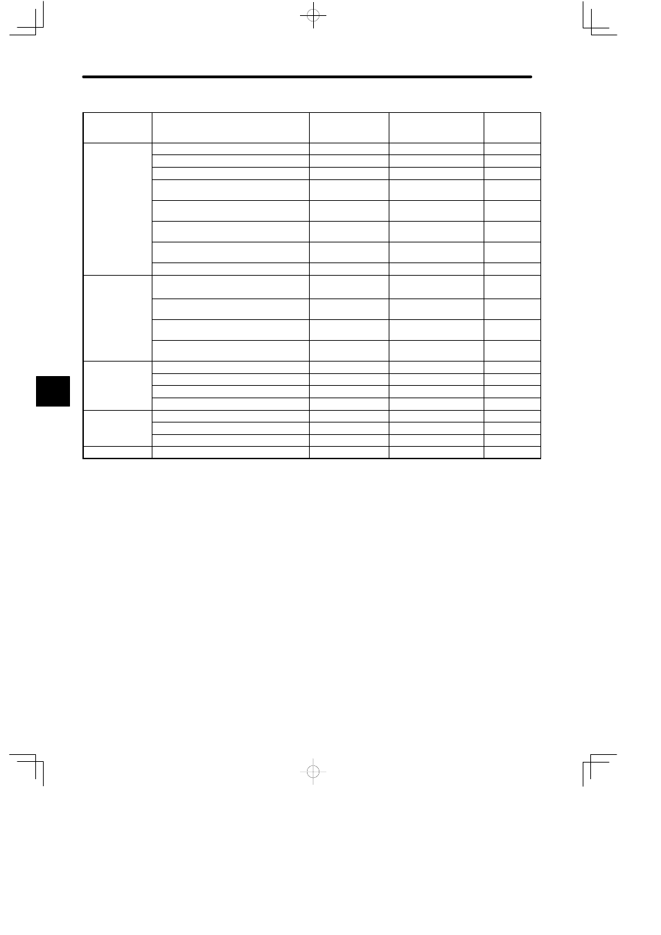
Product
Maximum
Heating
Value (W)
Model No.
Model Name
Name
Digital Output
M d l
100/200-VAC 8-point Output Module
ACOUT-8P
JAMSC-120DAO83000
9.0
g
p
Modules
100/200-VAC 16-point Output Module
ACOUT-16P
JAMSC-120DAO84300
5.5
12/24-VDC 8-point Output Module
DC24OUT-8P
JAMSC-120DDO33000
1.6
12/24-VDC 16-point Output Module
(sinking)
DC24OUT-16PSN
JAMSC-120DDO34310
7.1
12/24-VDC 16-point Output Module
(sourcing)
DC24OUT-16PSR
JAMSC-120DDO34320
7.5
12/24-VDC 32-point Output Module
(sinking)
DC24OUT-32PSN
JAMSC-120DDO35410
6.5
12/24-VDC 64-point Output Module
(sinking)
DC24OUT-64PSN
JAMSC-120DDO36410
13.0
Relay Contact 16-point Output Module
RELAY-16P
JAMSC-120DRA84300
3.1
Analog Output
Modules
Analog Output Module
(
±
10 V, 2 channels)
D/A-VOL-2CH
JAMSC-120AVO01000
2.0
Analog Output Module
(0 to 10 V, 2 channels)
D/A 0−10V 2CH
JAMSC-120AVO01100
2.0
Analog Output Module
(0 to 5 V, 2 channels)
D/A 0−5V 2CH
JAMSC-120AVO01200
2.0
Analog Output Module
(4 to 20 mA, 2 channels)
D/A-CUR-2CH
JAMSC-120ACO01000
2.5
Special Purpose
M d l
High-speed Counter Module (1 channel)
COUNTER-1CH
JAMSC-120EHC21110
1.8
p
p
Modules
Pulse Catch Module
COUNTER-16CH
JAMSC-120RD134400
6.0
Register Input Module
REGISTER-IN
JAMSC-120RDI34410
3.6
Register Output Module
REGISTER-OUT
JAMSC-120RDO34410
3.0
Motion Modules
One-axis Motion Module
MC10
JAMSC-120MMB10100 8.7
Four-axis Motion Module
MC20
JAMSC-120MMB10400 12.8
Two-axis Motion Module
MC15
JAMSC-120MMB20200 9.0
Other Modules
Expander Module
EXPANDER
JAMSC-120CBE37000
2.0
5.1.6 Mounting Base Layout
1) Determine the Mounting Base layout as described in this section to ensure efficient heat
dissipation from the Module and facilitate installation and removal of the Module and
Mounting Base.
a) The distance between the uppermost Mounting Base and devices (such as a molded-
case circuit breakers, electromagnetic switches, or relays) above the Mounting Base
or the control panel structure must be at least 80 mm.
5
