Yaskawa MEMOCON GL120 User Manual
Page 200
System Components: Functions and Specifications
4.4.6 MEMOBUS Modules (RS-422) cont.
— 4-144 —
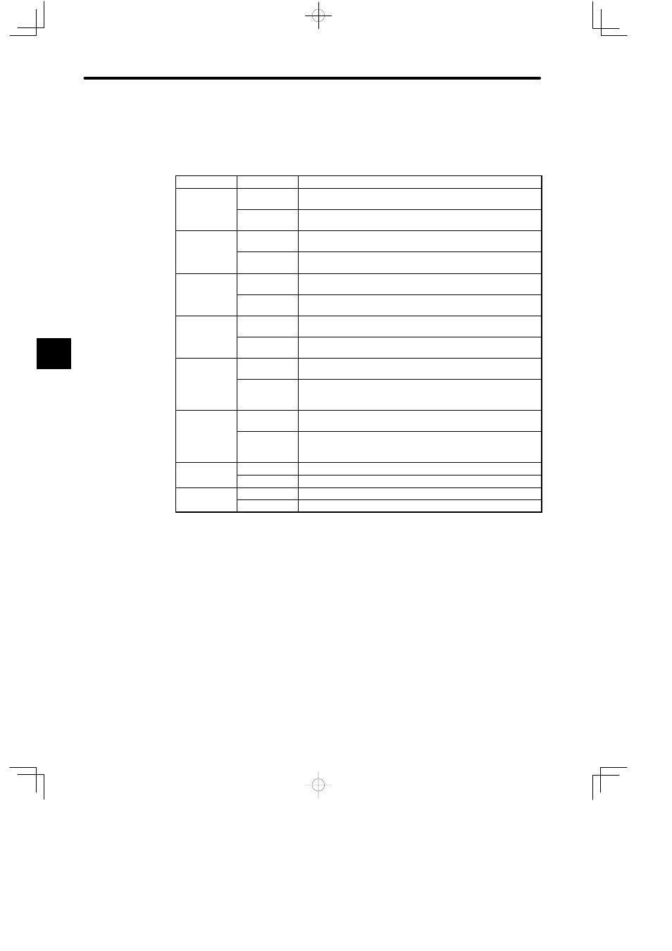
d) Each pin’s function is shown in the following table.
Table 4.61 Function of DIP Switch
Pin No.
Settings
Function
1
ON
Sets communications mode and parameters of Port 2 to the
defaults.
OFF
Sets communications mode and parameters of Port 2 to user
settings.
2
ON
Sets communications mode and parameters of Port 1 to the
defaults.
OFF
Sets communications mode and parameters of Port 1 to user
settings.
3
ON
When using Port 2 as master port, sets communications mode
to transparent mode.
OFF
When using Port 2 as master port, sets communications mode
to MEMOBUS mode.
4
ON
When using Port 1 as master port, sets communications mode
to transparent mode.
OFF
When using Port 1 as master port, sets communications mode
to MEMOBUS mode.
5
ON
Sets Port 2 as slave port. Master communications become
ineffective.
OFF
Sets Port 2 as combined master/slave port. Master
communications become effective. When using COMM
instruction for port 2, turn this pin OFF.
6
ON
Sets Port 1 as slave port. Master communications become
ineffective.
OFF
Sets Port 1 as combined master/slave port. Master
communications become effective. When using COMM
instruction for port 1, turn this pin OFF.
7
ON
Sets Module number to 2.
OFF
Sets Module number to 1.
8
ON
Sets Module to self diagnosis mode.
OFF
Sets Module to normal operation mode.
Note
When using two MEMOBUS Modules, do not use the same Module number. If you use the
same Module number, the following will result:
• If the two MEMOBUS Modules are mounted to the same Rack, the MEMOBUS Module
mounted to the slot with the larger slot number will not operate normally.
• If the two MEMOBUS Modules are mounted to different Racks, the MEMOBUS Module
mounted to the Rack with the larger Rack number will not operate normally.
e) The default communications mode and parameters are as follows:
(1) Communications mode: RTU mode
4