2 installing mounting bases and modules, 1 installing mounting bases – Yaskawa MEMOCON GL120 User Manual
Page 373
!
!
Installation and Wiring
5.2.1 Installing Mounting Bases
— 5-16 —
5.2
Installing Mounting Bases and Modules
This section describes how to install a Mounting Base and Modules in the control panel
and connect Rack-to-rack I/O Cables.
5.2.1
Installing Mounting Bases
5-16
. . . . . . . . . . . . . . . . . . . . . . . . . . . . . . . . . . . . . . . . .
5.2.2
Installing Modules
5-20
. . . . . . . . . . . . . . . . . . . . . . . . . . . . . . . . . . . . . . . . . . . . . . .
5.2.3
Installing the CPU and the Power Supply Module
5-25
. . . . . . . . . . . . . . . . . . . . .
5.2.4
Installing the Terminal Block for Field Connection Module
5-29
. . . . . . . . . . . . . .
5.2.5
Connector for Field Connections Module
5-35
. . . . . . . . . . . . . . . . . . . . . . . . . . . .
5.2.6
Installing the Communications Modules
5-39
. . . . . . . . . . . . . . . . . . . . . . . . . . . . .
5.2.7
Installing the Motion Module
5-44
. . . . . . . . . . . . . . . . . . . . . . . . . . . . . . . . . . . . . . .
5.2.8
Installing Rack-to-Rack I/O Cables
5-49
. . . . . . . . . . . . . . . . . . . . . . . . . . . . . . . . .
5.2.1 Installing Mounting Bases
Install a Mounting Base on the device mounting steel plate or DIN track inside the control pan-
el as described in this section.
WARNING
If the control panel in which the GL120 or GL130 is mounted is to be used in a place subject to
excessive vibration or is to be exported or transported over long distances, avoid installing
the Mounting Base on a DIN track. Instead, install it on a device mounting steel plate.
If a Mounting Base is installed on a DIN track, the Mounting Base may fall off the DIN track
when strong vibration or shock is applied to the control panel.
WARNING
Each module connector on the Mounting Base has a connector cover. When installing the
Mounting Base, leave the connector covers attached to prevent foreign matter from entering
the module connectors.
If foreign matter enters the module connectors, the GL120 or GL130 may malfunction.
1) Installing a Mounting Base on Device Mounting Steel Plate
a) Determine the Mounting Base layout as described in 5.1.6 Mounting Base Layout.
b) Open four Mounting Base mounting holes in the device mounting steel plate accord-
ing to the dimensional drawing of a Mounting Base shown in B.8 Mounting Bases.
A.2 Drilling Plan shows an example.
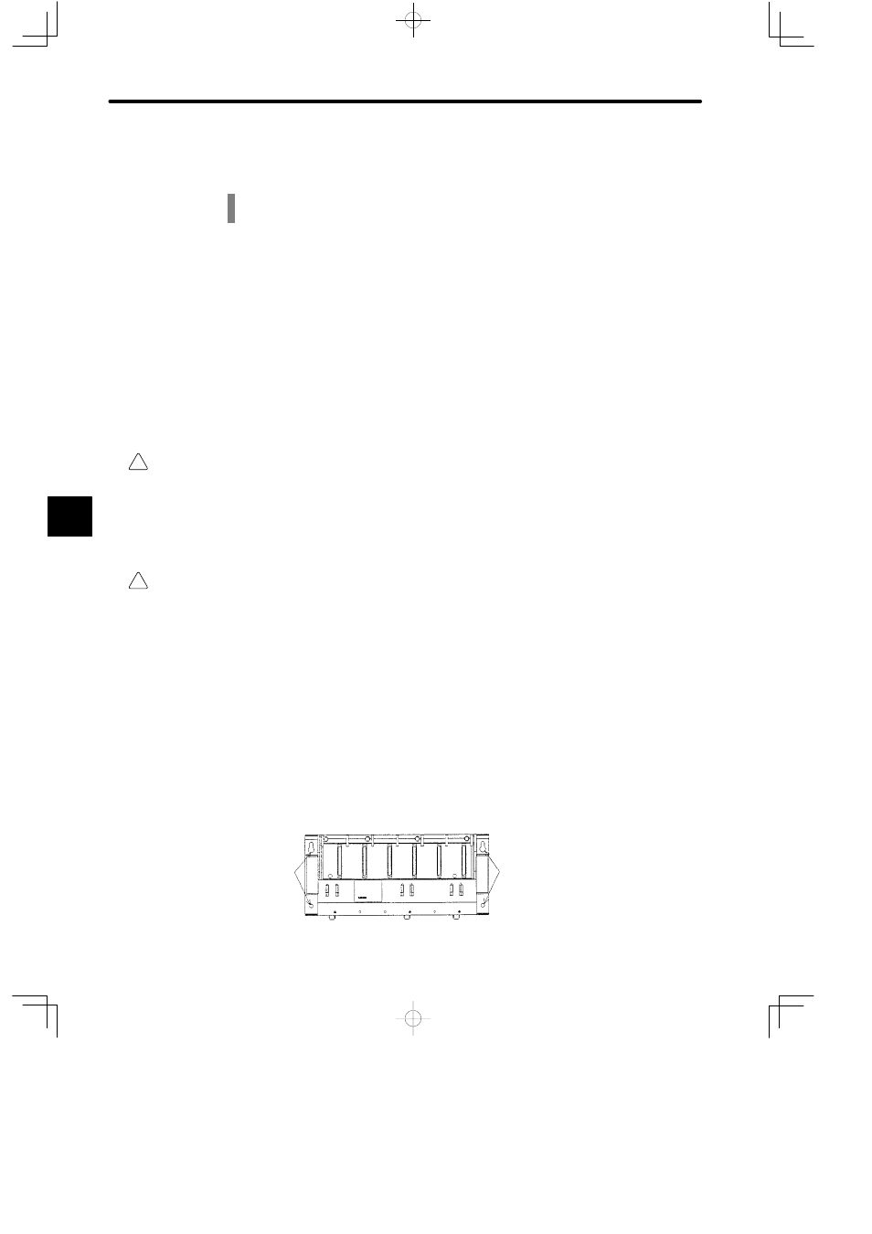
c) The Mounting Base has four mounting holes. Use four M5 screws to secure the
Mounting Base to the device mounting steel plate.
Mounting holes
Mounting holes
5