Yaskawa MEMOCON GL120 User Manual
Page 227
4.4 Communications Modules
— 4-171 —
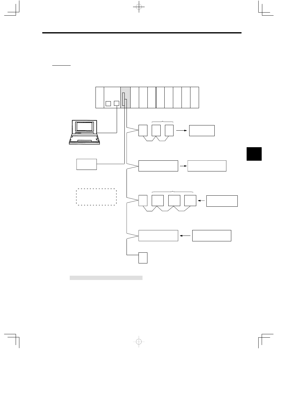
3) Example of Normal System Configuration
The following diagram shows an example of the system configuration when a Uniwire (H) I/F
is used in Normal System 200-m mode.
PS05:
AC Input Power Supply Module (3 A)
CPU20:
CPU Module (16 KW)
UNI(H):
Uniwire H-System Interface Module
DI:
12/24-VDC 16-point Input Module
DO:
12/24-VDC 16-point Output Module
MB12:
12-slot Mounting Base
AD-120:
Address Unit
PT-04S:
Power Terminal Unit (100 VAC, 0.5 A, triac
outputs, 4 circuits)
PTV-16T: Address-incorporated Power Terminal Unit
(24 VDC, 200 mA, transistor outputs with short-circuit
protection, 16 circuits)
ST-04A10: Sensor Terminal Unit (100 VAC, 4 circuits)
STV-16T: Address-incorporated Sensor Terminal Unit
(24 VDC, photocoupler isolation, 16 circuits)
100-VAC sensors
24-VDC, 200-mA loads
100-VAC, 0.5-A
loads
DI
UNI
DI
DI
M
P
CPU20
DO DO
DI
DI
Local channel/Rack 1 (CPU Rack)
Output Units (4 points ¢ 2 Units)
AD-
120
P120C
Programming
Panel
DC power
supply
(24 VDC)
W0203-02
PS
05
DO
For Uniwire
transmissions
#0
PT-
04S
PT-
04S
MB12
8 points
TC-05 (Terminal cable)
Address-incorporated
PTV-16T
#8
16 points
Input Units (4 points × 3 Units)
AD-
120
#24
ST-
04A10
12 points
TC-05 (Terminal cable)
ST-
04A10
ST-
04A10
Address-incorporated
STV-16T
#36
24-VDC sensors
16 points
ED-
120
End unit
Transmission cable
(Total length: 200 m)
Uniwire System address:
#0, #8, #24, #36.
Output Unit (16 points ¢ 1 Unit)
Input Unit (16 points ¢ 1 Unit)
(H)
Figure 4.47 Normal System Configuration Example
4
A
EXAMPLE
"