Yaskawa MEMOCON GL120 User Manual
Page 198
System Components: Functions and Specifications
4.4.6 MEMOBUS Modules (RS-422) cont.
— 4-142 —
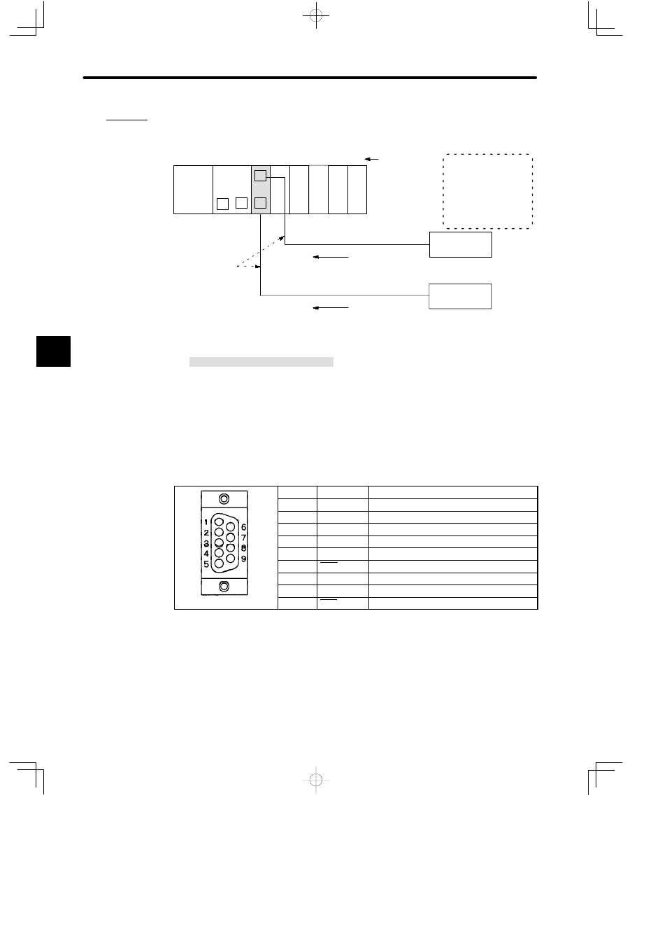
Example 4
Connecting ASCII Device (1:1 Communications)
PS10:
Power Supply Module (7 A)
CPU20:
CPU Module (16 KW)
MEM422: MEMOBUS Module (RS-422)
DI:
12/24-VDC 16-point Input Module
DO:
12/24-VDC 16-point Output Module
MB10:
10-slot Mounting Base
Communications by COMM instruction
DI
Set MEMOBUS port of
MEMOBUS Module thus:
D
Combined
master/slave port
D
transparent mode
Data input
M
PS10
DI
MEM
422
M
M
P
MB10
Slot No.
Local channel
Rack 1 (CPU Rack)
CPU20
1
2
3
4
5
6
7
8
9
10
DI
DO DO
Communications by COMM instruction
M
Bar code reader
Needs to be equipped with
RS-422 interface
Electronic scale
Shielded twisted
pair cable
(500 m max.)
Data input
Needs to be equipped with
RS-422 interface
Figure 4.36 Connecting ASCII Devices (1: 1 Communications)
d) The connector for a MEMOBUS port is a D-sub connector (9-pin, female). The con-
nector pin arrangement and signal names are shown in the following table:
Table 4.60 Pin Arrangement and the Signal Names
Pin No.
Symbol
Signal Name
1
PGND
Protective ground
2
TXD
Transmission data
3
RXD
Reception data
4
RXDRT
Receiver termination resistance:120 Ω
5
−
Not used
6
RXD
Reception data inversion
7
SGND
Signal ground
8
TXRD
Sender termination resistance:120 Ω
9
TXD
Transmission data inversion
4
A
EXAMPLE
"