Yaskawa MEMOCON GL120 User Manual
Page 311
4.7 Motion Modules
— 4-255 —
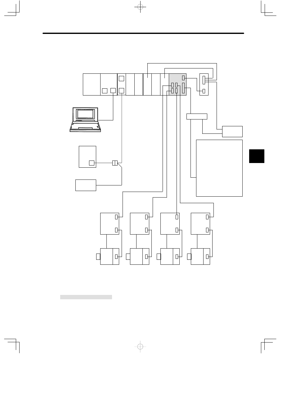
Example
System Configuration with a 4-axis Motion Module Controlling a Servomotor with an
Absolute Encoder
PS10:
Power Supply Module (7 A)
CPU30:
CPU Module (32 KW)
MEM232 MEMOBUS Module (RS-232)
DI:
12/24-VDC 16-point Input Module
DO:
12/24-VDC 16-point Output Module
MC20:
4-axis Motion Module
MB12:
12-slot Mounting Base
BM:
Battery Module (JRMSP-120XCP96000)
W0503-30:Servo cable (3.0 m)
W0401-03:Motion Module I/O Cable (3.0 m)
W0203-03:MEMOBUS Cable (2.5 m)
W0600-02:Teaching Pendant Cable (2.0 m)
W0601-02:Teaching Pendant Cable (2.0 m)
*1, *2:
See the technical documents on SERVOPACK.
*3 to *8:
To be prepared by user
XW2B-50Y:Terminal block connector
(manufactured by OMRON)
*7
*4
TB120
M
External I/O devices
1)
Limit switches, etc.
D
Positive overtravel
D
Negative overtravel
D
Zero signal
D
Deceleration signal
D
Skip input
2)
Relays
D
Brake output
DI
PS10
DI
M
P
CPU30
DO
DO
DI
Rack 1
(CPU Rack)
Teach
Pendant
P120C
Programming
Panel
SGDA
DC power
supply
24 VDC
MB12
W0203-03
BM
W0401-03
XW2B-50Y
*6
*5
*8
*3
SM
* 1: Motor cable
* 2: Encoder cable
Servomotor SGM
with absolute
encoder
MEM
232
M
M
DC power
supply
5 VDC
W0600-02
W0601-02
PG
Axis 1
SGDA
SM
PG
Axis 3
SGDA
SM
PG
Axis 4
SGDA
SM
*1
*2
PG
Axis 2
Servo amplifier:
SERVOPACK
compatible with
absolute/incremental
encoder
MC20
M: MEMOBUS port
W0503-30
Figure 4.77 A 4-axis Motion Module Controlling Servomotor with Absolute Encoder
4