Yaskawa MEMOCON GL120 User Manual
Page 424

!
5.3 Panel Wiring
— 5-67 —
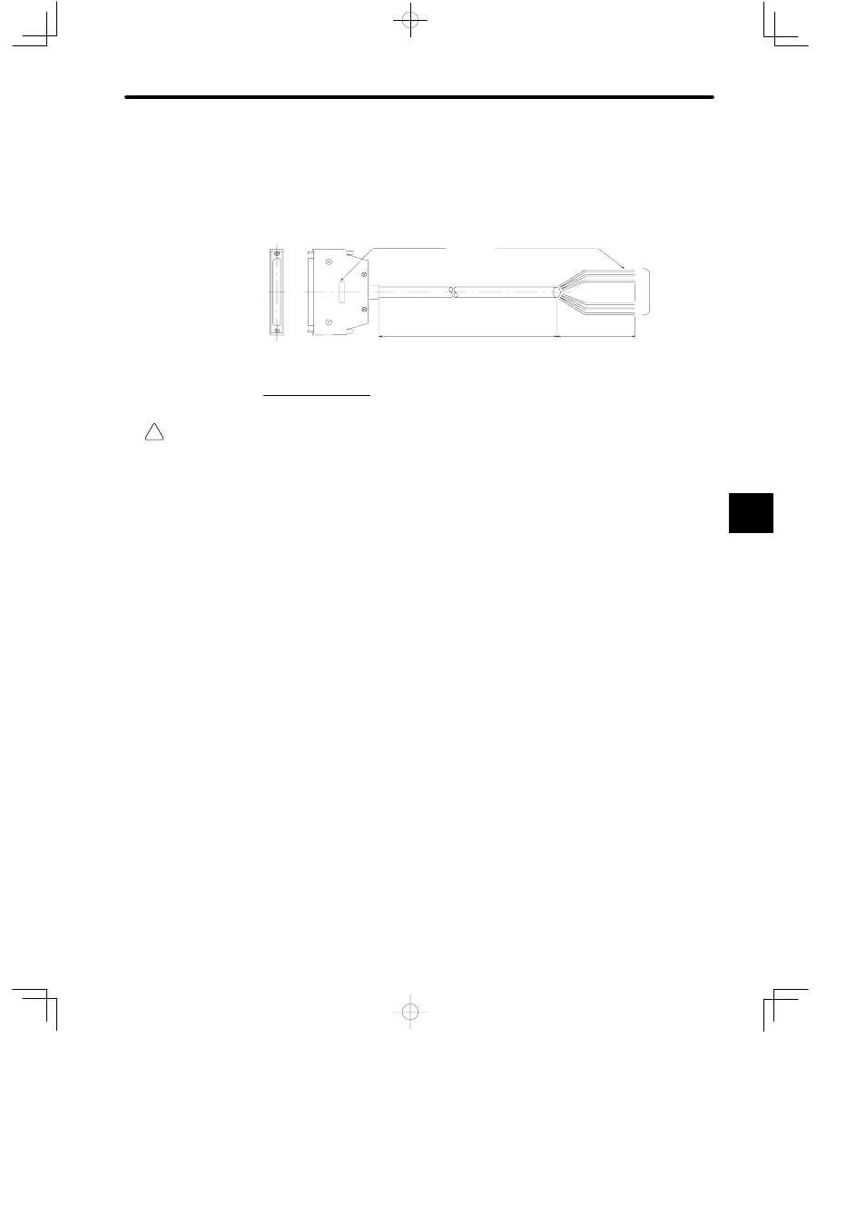
As shown in the figure below, the external device end of the W5410 cable is divided into
individual wires.
The Cable size is 0.2 mm
2
.
Pin number is attached
to each wire.
Connector (Module side)
Cable description
Shielded cable
Separate wires (external device end)
L
100 mm
40 separate
wires
3. Protective Fuse
WARNING
When using one of the following Output Modules, connect an external fuse corresponding to
the specifications of load and in series with load.
100/200-VAC 8-point Output Module (Model No.: JAMSC-120DAO83000)
100/200-VAC 16-point Output Module (Model No.: JAMSC-120DAO84300)
12/24-VDC16-point Output Module (sinking) (Model No.: JAMSC-120DDO34310)
12/24-VDC16-point Output Module (sourcing) (Model No.: JAMSC-120DDO34320)
12/24-VDC 32-point Output Module (sinking) (Model No.: JAMSC-120DDO35410)
12/24-VDC 64-point Output Module (sinking) (Model No.: JAMSC-120DDO36410)
Relay Contact 16-point Output Module (Model: JAMSC-120DRA84300)
Not connecting an external fuse may result in fire, damages to the device, and damages to
output circuits due to overload or a short-circuit at the load.
5
