Yaskawa MEMOCON GL120 User Manual
Page 31
2.1
Overview of the MEMOCON GL120 and GL130
— 2-7 —
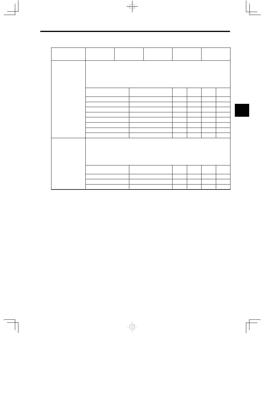
Item
CPU35
(DDSCR-
130CPU54110)
CPU30
(DDSCR-
130CPU54100)
CPU21
(DDSCR-
120CPU34110)
CPU20
(DDSCR-
120CPU34100)
CPU10
(DDSCR-
120CPU14200)
Maximum number
of coils, relays, etc.
1) When the number of data registers is the initial value, the following condition must be
met:
(Number of coils) + (Number of relays) ≤ 65,520.
2) The maximum value for each reference can be freely set within the above limit from the
Programming Panel (Unit: point (1 point = 1 bit)).
Item
Setting range
Setting
unit
Defaults
Example
1
Example
2
Coils
16 to 65,472
16
8,192 57,328 65,472
Link coils
0 to 4,096
1,024
2,048
2,048
0
MC coils
0 to 512
256
512
512
0
MC control coils
0 to 320
160
320
320
0
Input relays
16 to 65,472
16
1,024
4,096
16
MC relays
0 to 512
256
512
512
0
MC control relays
0 to 512
256
512
512
0
M code relays
0 to 192
96
192
192
0
Maximum capacity
of data register
1) When the number of coils and relays is the initial value, the number of words of holding
registers plus the number of words of constant registers plus the number of words of link
registers must not exceed 25,998.
2) The maximum value for each reference can be freely set within the above limit from the
Programming Panel (Unit: word (1 word = 16 bits)).
Setting range
Setting
unit
Defaults
Example
1
Example
2
Holding register
1 to 25,995
1
9,999 19,854 25,995
Constant register
1 to 4,096
1
4,096
4,096
1
Link register
0 to 4,096
1,024
2,048
2,048
0
2