Yaskawa MEMOCON GL120 User Manual
Page 112
System Components: Functions and Specifications
4.3.3 Specifications of CPU Modules cont.
— 4-56 —
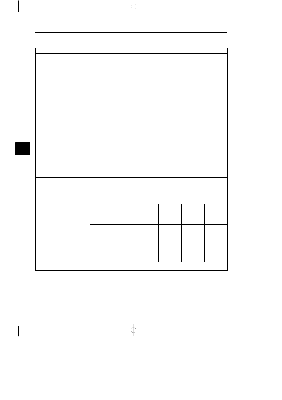
Item
Specifications
Program Memory Capacity
16K words (1 word: 24 bits)
Maximum I/O Points
1) Digital I/O points: 1,024 points max. (1 point: 1 bit)
2) I/O registers: 512 registers max. (1 register: 16 bits)
3) Local I/O:
D
Number of channels: 1
D
Number of Racks: 4 Racks max. including CPU Rack.
D
Number of mountable I/O Modules: 54 Modules max.
The total number of remote I/O points and registers must meet the above conditions
1) and 2).
4) Remote I/O:
D
Number of channels: 2
D
Number of stations per channel: 15
D
Number of Racks per channel: Max. 4 Rack
D
Number of I/O points per station:
(Digital input points ÷ 8) + (Input registers x 2) ≤ 512 bytes
(Digital output points ÷ 8) + (Output registers x 2) ≤ 512 bytes
The total number of remote and local I/O points and registers must meet the above
conditions 1) and 2).
Maximum Points of Coils and
Relays
1) When the number of data registers is the initial value, the following condition must
be met:
(Number of coils) + (Number of relays) ≤ 65,520
2) The maximum value of each reference can be freely set within the above limit from
the Programming Panel (Unit: point (1 point = 1 bit)).
Coil/Relay
Setting range
Setting unit
Defaults
Example 1
Example 2
Coils
16 to 65,472
16
8,192
60,400
65,472
Link coils
32 to 4,096
1,024
2,048
2,048
32
MC coils
0 to
65,
512
256
512
512
0
MC control
coils
0 to
65,
320
160
320
320
0
Input relays
16 to 65,472
16
1,024
1,024
16
MC relays
0 to
65,
512
256
512
512
0
MC control
relays
0 to
65,
512
256
512
512
0
M code
relays
0 to
65,
192
96
192
192
0
Note: Number of I/O allocatable input relays = 1024 − (Number of output coils which
have been allocated)
4