11 m-net module, Appearance – Yaskawa MEMOCON GL120 User Manual
Page 238
System Components: Functions and Specifications
4.4.11 M-NET Module
— 4-182 —
8) Related Manuals
Before operating your Distributed I/O Driver Module, read the following manual carefully
and be sure that you fully understand the information on specifications, applications
methods, safety precautions, etc.
MEMOCON GL120, GL130 Distributed I/O Driver Module User’s Manual
(SIEZ-C825-70.29)
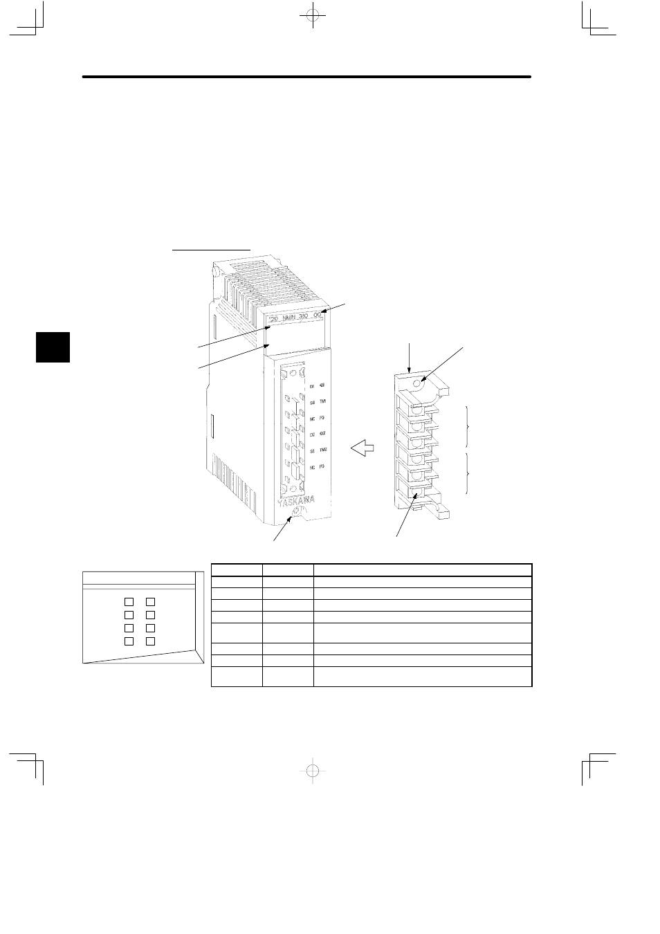
4.4.11 M-NET Module
1. Appearance
Removable
terminal block
Terminal block
mounting screw (use
M3 Phillips
screwdriver.)
Port 1
Field wiring terminal
(use M3 Phillips screwdriver.)
Module description
(120NMN31000)
Color code
(yellow)
LED area
Port 2
Module mounting screw
(use M4 Phillips screwdriver.)
LED
Color
Indication when ON
READY
Green
Module is operating normally.
ACTIVE
Green
Module is being serviced by CPU Module.
TX1
Green
Module is sending data from port 1.
RX1
Green
Module is receiving data from port 1.
ERR1
Red
An error has occurred in the Module transmission from
port 1.
TX2
Green
Module is sending data from port 2.
RX2
Green
Module is receiving data from port 2.
ERR2
Red
An error has occurred in the Module transmission from
port 2.
Figure 4.52 Appearance of M-NET Module
4
TX1
READY
120 NMN 310 00
RX1
ERR1
ACTIVE
TX2
RX2
ERR2
LED Area