Yaskawa MEMOCON GL120 User Manual
Page 336
System Components: Functions and Specifications
4.8.1 Expander Module cont.
— 4-280 —
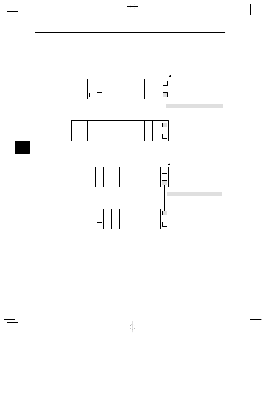
(2) The following example shows how to use Rack-to-rack I/O cable connectors and
an Rack-to-rack I/O Cable.
Example 1
DI
EXP
DI
PS
05
EXP
PS10
DO
DI
M
P
MB12
Slot No.
Rack-to-rack I/O Cable
W0100-02
(0.2m)
MC20
MC20
Rack 2
Rack 1 (CPU Rack)
DI
DI
DI
DI
DI
DO DO DO DO
MB12
CPU30
1
2
3
4
5
6
7
8
9
10
11
12
1
2
3
4
5
6
7
8
9
10
11
12
Example 2
PS10:
Power Supply Module (7 A)
PS05:
Power Supply Module (3 A)
CPU30:
CPU Module (32 KW)
MC20:
4-axis Motion Module
DI:
12/24-VDC 16-point Input Module
DO:
12/24-VDC 16-point Output Module
EXP:
Expander Module
MB12:
12-slot Mounting Base
DI
EXP
DI
PS
05
EXP
PS10
DO
DI
M
P
MB12
Slot No.
Rack-to-rack I/O Cable
W0100-02
(0.2m)
MC20
MC20
Rack 1 (CPU Rack)
Rack 2
DI
DI
DI
DI
DI
DO DO DO DO
MB12
CPU30
1
2
3
4
5
6
7
8
9
10
11
12
1
2
3
4
5
6
7
8
9
10
11
12
Figure 4.85 Using Rack-to-rack I/O Cables and Cable Connectors
d) Rack Number Setting Switch
(1) The Rack number setting switch is a rotary switch with positions 0 to 9. It is used to
set the Rack No.
4
A
EXAMPLE
"