Yaskawa MEMOCON GL120 User Manual
Page 33
2.1
Overview of the MEMOCON GL120 and GL130
— 2-9 —
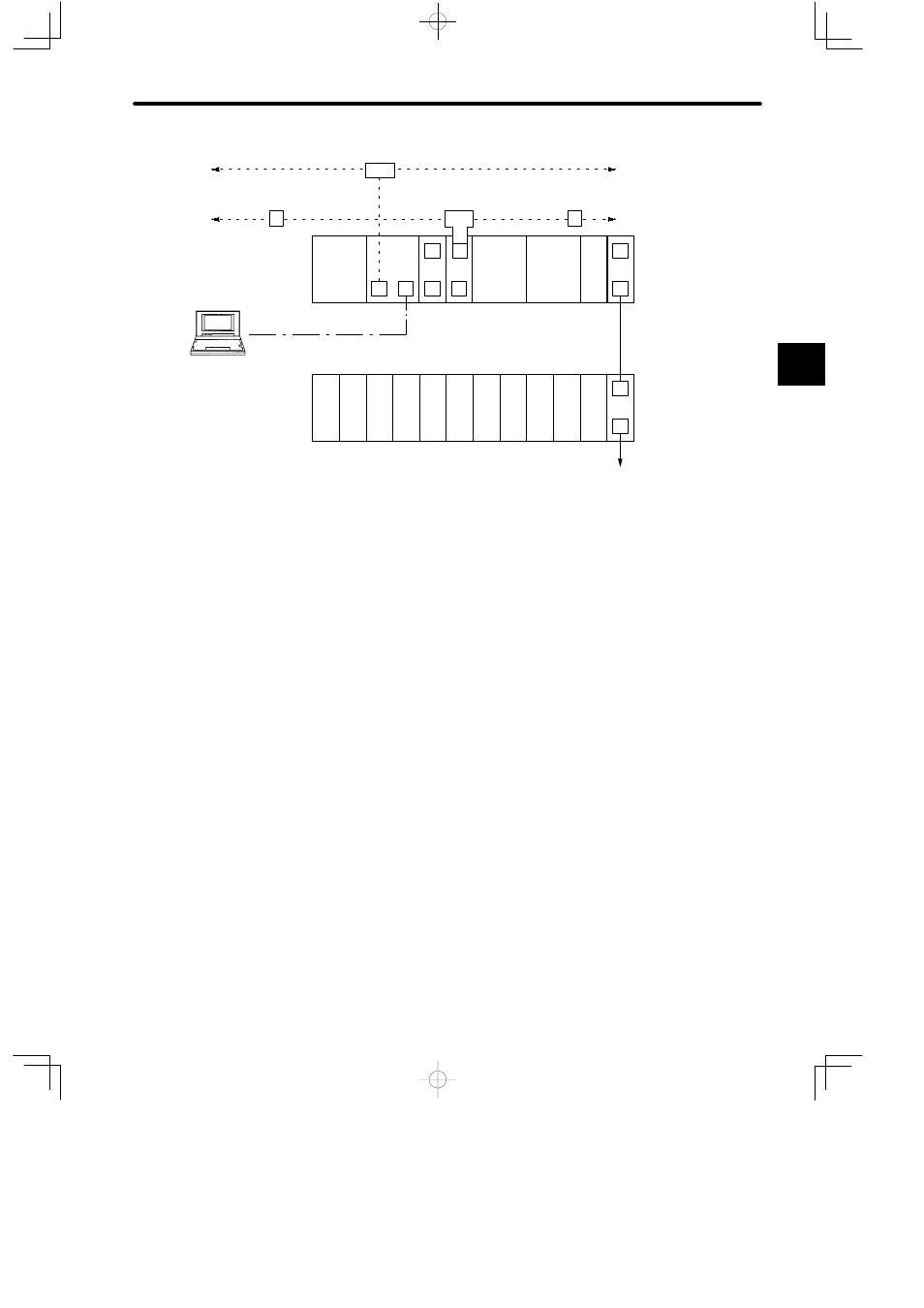
Previous node
Previous station
(DOS computer running
MEMOSOFT)
EXP
I/O
I/O
I/O
I/O
I/O
I/O
I/O
I/O
PS
05
EXP
I/O
CPU20
PS10
C
LNC
M
MEM
232
M
M
M
P
MB12
MB12
HUB
A
GL120
MEMOBUS PLUS Cable
PC Link Cable
Next station
W0202-02
W0100-02
T
A
Station 2
I/O
I/O
MC20
MC20
Can be extended up to Rack 4.
Local channel
Rack 2
Local channel
Rack 1
(CPU Rack)
Next node
1) Legend
PS10:
Power Supply Module
(7 A)
MC20:
4-axis Motion
Module
HUB: Hub Module
PS05:
Power Supply Module
(3 A)
I/O:
Input/Output
Module
T:
T-adapter
CPU20:
CPU Module (16 KW)
EXP:
Expander
Module
R:
Terminator
CPU30:
CPU Module (32 KW)
MB10:
10-slot Mounting
Base
A:
Conversion
Adapter
RDC:
Remote I/O Driver
Module
MB12:
12-slot Mounting
Base
P:
MEMOBUS
PLUS port
RRC:
Remote I/O Receiver
Module
W0100-02:
Rack-to-rack I/O
Cable
M:
MEMOBUS
port
LNC:
PC Link Module
W0202-02:
MEMOBUS
Cable
C:
Coaxial cable
communica-
MEM232: MEMOBUS Module
(RS-232)
W0203-02:
MEMOBUS
Cable
co
ca
tions port
MEM422: MEMOBUS Module
(RS-422)
MEMOSOFT: Programming
device
2) The following five types of Mounting Base are available. Up to four Mounting Bases can
be used for each station.
D
MB06: 6-slot Mounting Base
D
MB12: 12-slot Mounting Base
D
MB08: 8-slot Mounting Base
D
MB16: 16-slot Mounting Base
D
MB10: 10-slot Mounting Base
2