Yaskawa MEMOCON GL120 User Manual
Page 197
4.4 Communications Modules
— 4-141 —
Example 3
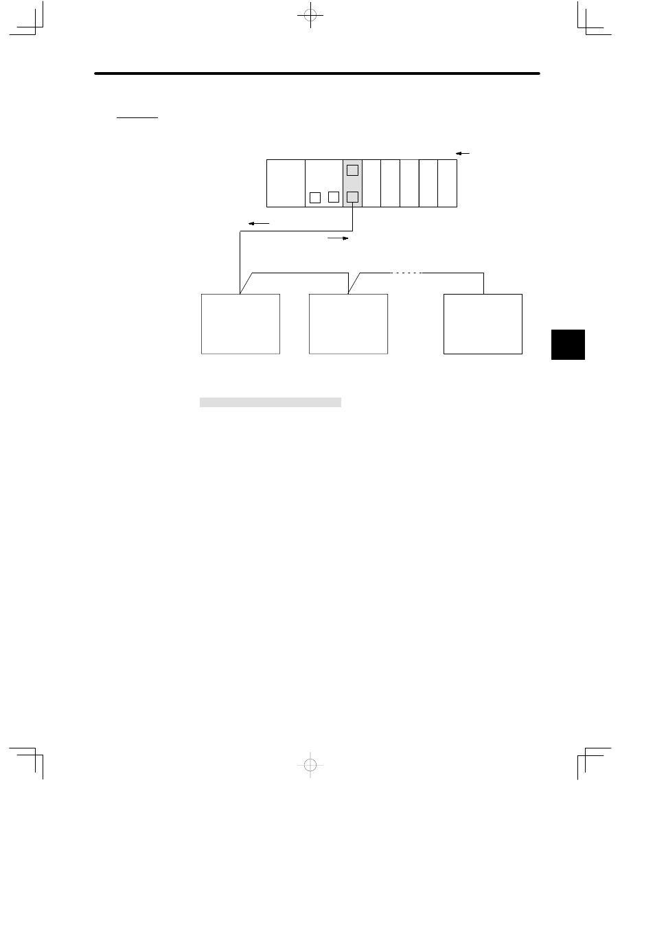
Connecting VS-616G3 plus Inverters (1:31 Communications)
Malfunctions,
operation conditions
PS10:
Power Supply Module (7 A)
CPU20:
CPU Module (16 KW)
MEM422: MEMOBUS Module (RS-422)
DI:
12/24-VDC 16-point Input Module
DO:
12/24-VDC 16-point Output Module
MB10:
10-slot Mounting Base
DI
M
PS10
DI
MEM
422
M
M
P
MB10
Slot No.
Local channel
Rack 1 (CPU Rack)
CPU20
1
2
3
4
5
6
7
8
9
10
DI
DO DO
M
* MEMOBUS ports of MEMOBUS Module
are set to combined master/slave ports.
Speed data,
operation references
Inverter
VS-616G3 plus
(Inverter which
supports MEMOBUS
communications)
(Slave Address 2)
Inverter
VS-616G3 plus
(Inverter which
supports MEMOBUS
communications)
(Slave Address 1)
Inverter
VS-616G3 plus
(Inverter which
supports MEMOBUS
communications)
(Slave Address 31)
Shielded twisted pair cable (500 m max.)
Figure 4.35 Connecting VS-616G3 Plus Inverters (1:31 Communications)
4
A
EXAMPLE
"