Yaskawa MEMOCON GL120 User Manual
Page 137
4.3 CPU Modules
— 4-81 —
2. Operations Different from CPU20
The operation of the following items, which are used differently, are described in this section.
• DIP switch
• PC Card slot
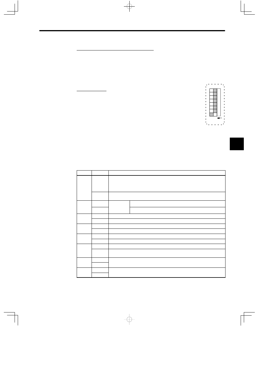
3. DIP Switch
1) The DIP switch consists of 8 pins. The pins are numbered from 1 to 8,
as shown in the diagram.
2) Each pin turns ON when it is moved to the left (toward the key switch).
3) Pins are effective at the following times:
a) Pins 1 to 3: Whenever the pin is turned ON.
b) Pin 5: When power is turned ON to the Power Supply Module on the CPU Rack.
4) Each pin’s function is shown in the following table. Refer to following pages for details.
Table 4.26 Function of DIP Switch Pins
Pin No.
Setting
Function
1
ON
1) Sets communications mode of MEMOBUS port according to the setting
of pin 2.
2) Sets communications parameter of MEMOBUS port to defaults.
OFF
Sets communications mode and parameters of MEMOBUS port to the user
settings.
2
ON
Effective
when pin 1
Sets communications mode of MEMOBUS port to ASCII.
OFF
when pin 1
is ON.
Sets communications mode of MEMOBUS port to RTU.
3
ON
Sets the CPU Module to bridge mode.
OFF
Releases the CPU Module from bridge mode.
4
ON
Set when a PC Card is used.
OFF
Set when a PC Card is not used.
5
ON
Sets start mode of CPU Module to automatic RUN operation.
OFF
Sets start mode of CPU Module to normal operation.
6
ON
Set when all ROM operation files are to be read. (See note.)
OFF
Set when ROM operation files other than those containing reference data
are to be read.
7
ON
For future use. It does not matter whether the pin is turned ON or OFF.
OFF
p
8
ON
For future use. It does not matter whether the pin is turned ON or OFF.
OFF
p
Note ROM operation is a function by which the CPU Module reads ladder logic programs at power
ON and controls the relevant devices. The CPU21 Module reads the ladder logic programs
from the PC Cards.
4
1
234567
8
O N