9 uniwire h-system interface module, Appearance – Yaskawa MEMOCON GL120 User Manual
Page 222
System Components: Functions and Specifications
4.4.9 Uniwire H-system Interface Module
— 4-166 —
4.4.9 Uniwire H-system Interface Module
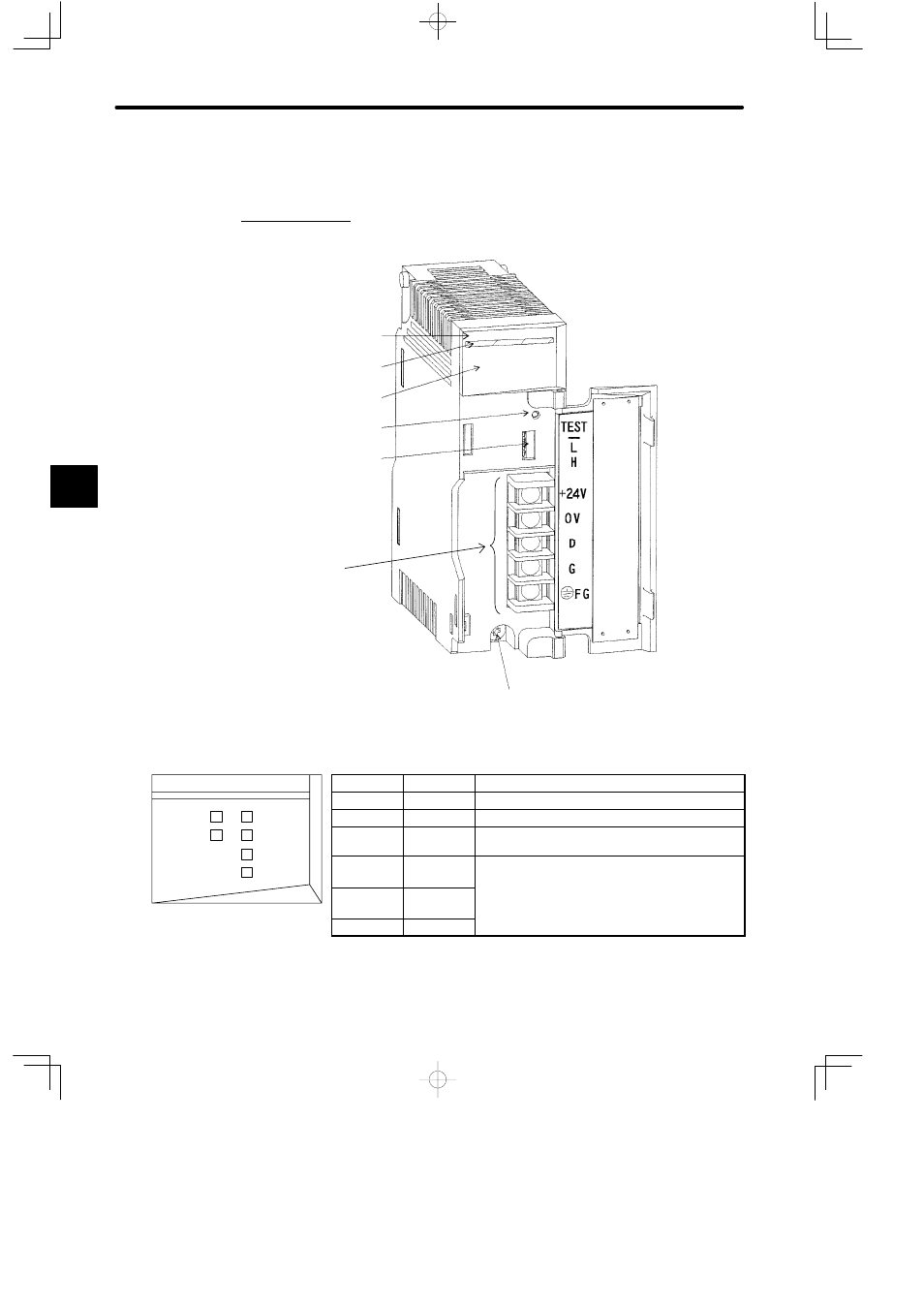
1. Appearance
External wiring
terminals (use M3.5
Phillips screwdriver.)
DIP switches
Module Description
(120CRD21120)
Color code (yellow)
LED area
Reset switch
Module mounting screw
(Use M4 Phillips screwdriver.)
20
120 CRD 211
LED
Color
Indication when ON
READY
Green
Module is operating normally.
ACTIVE
Green
Module is being communicated by CPU Module.
SEND
Green
Module is communicating by Uniwire System.
(Light flashes.)
ERR1
Red
D
An error has occurred either in the Module or in
the Uniwire System.
ERR2
Red
y
D
See the following table.
ERR3
Red
Figure 4.45 Appearance of Uniwire (H) I/F Module
4
SEND
READY
120 CRD 211 20
ACTIVE
ERR1
ERR2
ERR3
LED area
This manual is related to the following products: