Yaskawa MEMOCON GL120 User Manual
Page 164
System Components: Functions and Specifications
4.4.2 Remote I/O Driver Module cont.
— 4-108 —
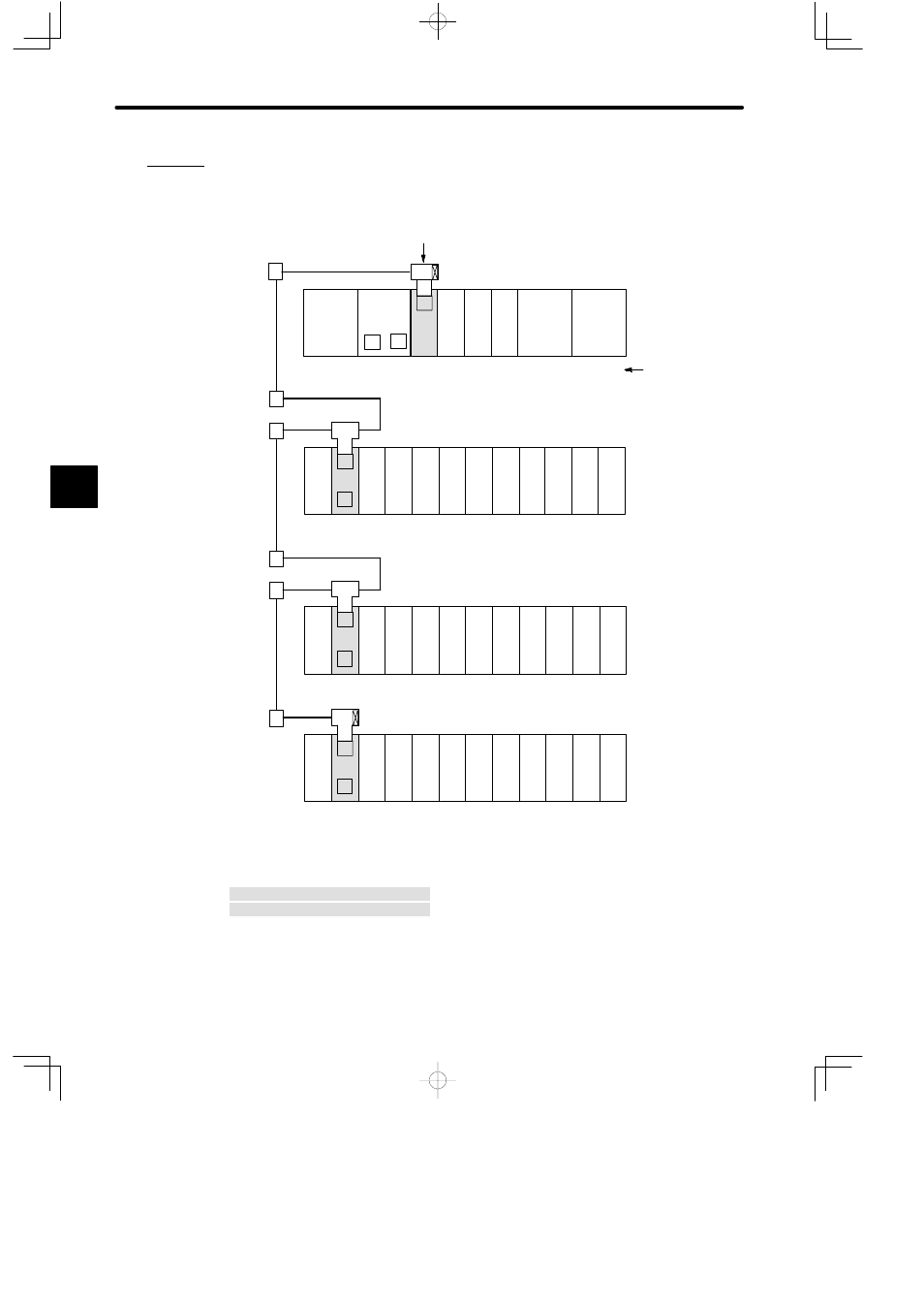
Example
Connecting a Remote I/O Driver Module and Remote I/O Receiver Modules
PS10:
Power Supply Module (7 A)
PS05:
Power Supply Module (3 A)
CPU30:
CPU Module (32 KW)
RDC:
Remote I/O Driver Module
RRC:
Remote I/O Receiver Module
DI:
12/24-VDC 16-point Input Module
DO:
12/24-VDC 16-point Output Module
MC20:
4-axis Motion Module
MB12:
12-slot Mounting Base
Rack 1 (Receiver
Rack)
M
DI
DI
PS
05
RDC
PS10
DO
DI
P
MB12
Slot No.
MC20
MC20
Rack 1 (CPU Rack)
DI
DI
DI
DI
DI
DO
MB12
CPU30
1
2
3
4
5
6
7
8
9
10
11
12
1
2
3
4
5
6
7
8
9
10
11
12
A
A
Conversion
Adapter
Branch line coaxial cable*1
T-adapter
R (Terminator)
Local channel
Main line
coaxial cable*2
Remote channel 1, station 1
DO DO DO
RRC
M
A
T
*1
*1
Rack 1 (Receiver
Rack)
DI
PS
05
DI
DI
DI
DI
DI
DO
MB12
1
2
3
4
5
6
7
8
9
10
11
12
A
Remote channel 1, station 2
DO DO DO
RRC
M
A
*1
*1
Rack 1 (Receiver Rack)
DI
PS
05
DI
DI
DI
DI
DI
DO
MB12
1
2
3
4
5
6
7
8
9
10
11
12
Remote channel 1, station 3
DO DO DO
RRC
M
A
*1
*2
*2
T
C
T
C
T
C
T
C
DO
R
Figure 4.24 Connecting Remote I/O Driver/Receiver Modules
4
A
EXAMPLE
"