3 cpu modules, 1 appearance of cpu modules – Yaskawa MEMOCON GL120 User Manual
Page 80
System Components: Functions and Specifications
4.3.1 Appearance of CPU Modules
— 4-24 —
4.3
CPU Modules
This section describes the functions, models, specifications, and other information on
the CPU Modules.
4.3.1
Appearance of CPU Modules
4-24
. . . . . . . . . . . . . . . . . . . . . . . . . . . . . . . . . . . . . .
4.3.2
CPU Modules: Functions and Models
4-30
. . . . . . . . . . . . . . . . . . . . . . . . . . . . . . .
4.3.3
Specifications of CPU Modules
4-35
. . . . . . . . . . . . . . . . . . . . . . . . . . . . . . . . . . . .
4.3.4
Using CPU Modules 1 (For CPU20, CPU30, and CPU35)
4-65
. . . . . . . . . . . . .
4.3.5
Using CPU Modules 2 (For CPU21)
4-80
. . . . . . . . . . . . . . . . . . . . . . . . . . . . . . . .
4.3.6
Using CPU Modules 3 (For CPU10)
4-88
. . . . . . . . . . . . . . . . . . . . . . . . . . . . . . . .
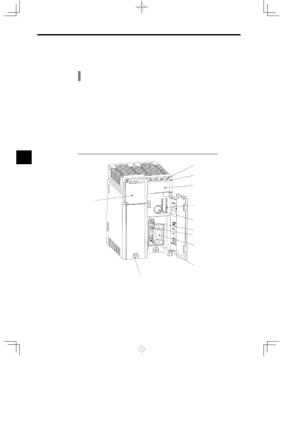
4.3.1 Appearance of CPU Modules
1. Appearance of CPU20 (Model No. DDSCR-120CPU34100)
Built-in battery
DIP switch
Key switch
Rotary switch 1
MEMOBUS port
MEMOBUS PLUS port
Module description
(120CPU34100)
Color code (yellow)
LED area
Module mounting screw
(Use M4 Phillips screwdriver.)
Rotary switch 2
4