Yaskawa MEMOCON GL120 User Manual
Page 298
System Components: Functions and Specifications
4.6.3 Pulse Catch Module cont.
— 4-242 —
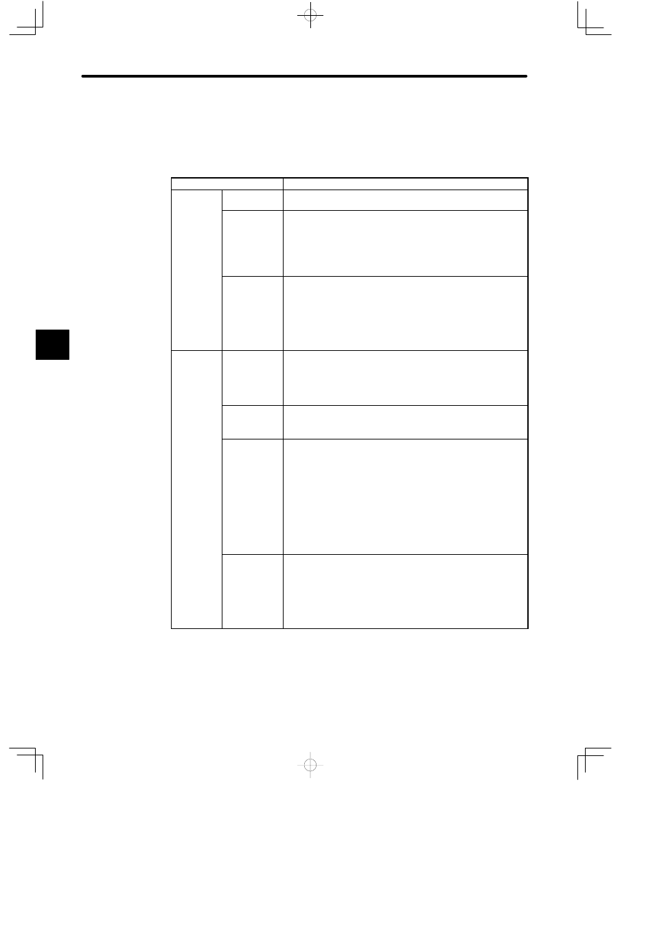
2) Performance Specifications
The following table shows the performance specifications of the Pulse Catch Module.
Table 4.100 Performance Specifications of Pulse Catch Module
Items
Specifications
Pulse Catch
Function
No. of Input
Circuits
16
Function
Minimum ON
Signal Width
1) With 8 Count Mode channels: 1 ms
2) With 16 Count Mode channels: 2 ms
Sixteen points can be used to catch pulses when either 8 or 16
Count Mode channels are specified.
Internal
Control
Signals
The following signals can be output to the Pulse Catch and
Counter Module from the ladder logic program.
RUN enable:
External input is enabled on the Pulse Catch and Counter Module
while this signal is ON. A signal can be set for every external input
circuit.
Counter
Function
No. of Input
Channels
16 channels (max.)
1) With 8 Count Mode channels: 8 channels max.
2) With 16 Count Mode channels: 16 channels max.
Maximum
Input Signal
Frequency
1) With 8 Count Mode channels: 500 Hz
2) With 16 Count Mode channels: 250 Hz
Internal
Control
Signals
The following signals can be output to the Pulse Catch and
Counter Module from the ladder logic program.
1) Counter enable:
External input is enabled on the Pulse Catch and Counter
Module while this signal is ON. A signal can be set for every
external input circuit.
2) Clear:
The count from the counter function will be cleared when this
signal turns ON.
Monitor
Function
The following signal can be monitored from the ladder logic
program.
Carry:
This signal stays ON for only a few scans after the count passes
FFFF(h) and returns to 0 if the counter function is in Absolute
Mode.
4