Yaskawa MEMOCON GL120 User Manual
Page 82
System Components: Functions and Specifications
4.3.1 Appearance of CPU Modules cont.
— 4-26 —
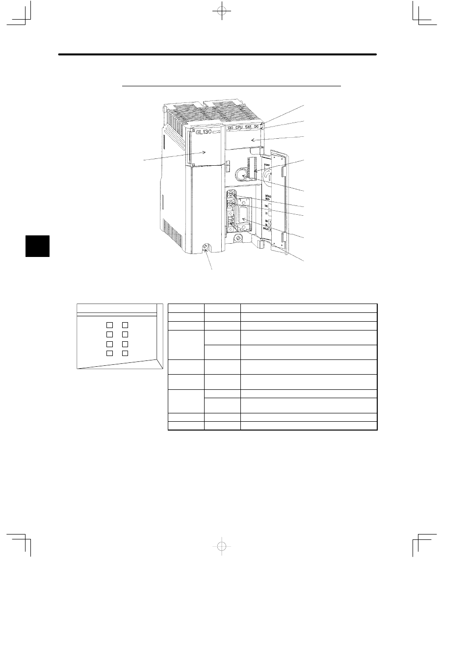
2. Appearance of CPU30 (Model No. DDSCR-130CPU54100)
Built-in battery
DIP switch
Key switch
Rotary switch 1
MEMOBUS port
MEMOBUS PLUS port
Module description
(130CPU54100)
Color code (yellow)
LED area
Rotary switch 2
Module mounting screw
(Use M4 Phillips screwdriver.)
LED
Color
Indication when ON
READY
Green
CPU Module is normal.
RUN
Green
CPU Module is running.
MB+/ERR
Green
MEMOBUS PLUS port is transmitting/receiving
data normally.
Red
Transmitting/receiving error has occurred in
MEMOBUS PLUS port.
BAT ALM
Red
Voltage in the built-in battery in CPU Module is
running down.
ACTIVE
Green
Access to CPU Module from other Module is
possible.
TX/ERR
Green
MEMOBUS port is transmitting data normally.
/
Red
Transmitting/receiving error has occurred in
MEMOBUS port.
RX
Green
MEMOBUS port is receiving data normally.
MEM PRT
Green
Key switch has selected memory protect ON.
Figure 4.9 Appearance of CPU30
Note
Make sure to replace the battery in the CPU Module within two weeks after the BAT ALM indi-
cator lights (replacement battery: BR-2/3A-1).
Programs or data stored in the CPU Module or Motion Modules will be lost if replacement is
delayed.
4
RUN
READY
130 CPU 541 00
MB+/ERR
BAT ALM
ACTIVE
TX/ERR
RX
MEM PRT
LED area