Yaskawa MEMOCON GL120 User Manual
Page 371
Installation and Wiring
5.1.7 Module Mounting Dimensions cont.
— 5-14 —
Table 5.4 Module Mounting Depths
Name
Depth of Module
(
)
Depth for
C
i
Module Mounting Depth
p
(mm)
p
Connection
Cable (mm)
Dimension D1
(mm)
Dimension D2
(mm)
Remote I/O Driver
Module
103.9
36.9
Approx. 158
Approx. 164
Remote I/O Receiver
Module
103.9
36.9
Approx. 158
Approx. 164
2000-Series Remote
I/O Driver Module
103.9
36.9
Approx. 158
Approx. 164
PC Link Module
103.9
37.0
Approx. 158
Approx. 164
M-NET Module
103.9
39.5
Approx. 161
Approx. 167
YENET 1600-D
Module
103.9
11.0
Approx. 132
Approx. 138
Optical/Electrical
Conversion Module
103.9
Determined according to the type of optical cable
used.
One-axis Motion
Module MC10
103.9
80.2
Approx. 202
Approx. 208
Four-axis Motion
Module MC20
100.3
81.0
Approx. 199
Approx. 205
Two-axis Motion
Module MC15
100.3
81.0
Approx. 199
Approx. 205
64-point I/O Module
103.9
87.0
Approx. 208
Approx. 214
Pulse Catch Module
103.9
87.0
Approx. 208
Approx. 214
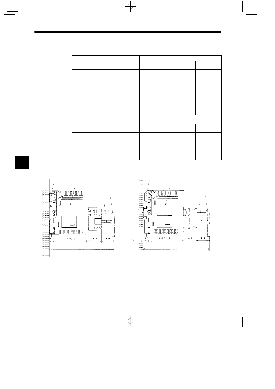
Mounting Base
Mounting Base
Device
mounting
steel
plate
(Dimension D1)
(Dimension D2)
Approx. 199
Approx. 205
DIN track
4-axis Motion Module
4-axis Motion Module
Motion Module I/O cable
Motion Module I/O cable
Servo cable
Servo cable
Device
mounting
steel
plate
Example 3
Example 4
5